The 4th generation French minivan Renault Espace was produced in 2002, 2003, 2004, 2005, 2006, 2007, 2008, 2009, 2010, 2011, 2012, 2013 and 2014. During this period, the car received several restyling. The extended version is called Renault Grand Espace. We propose to get acquainted with the locations of all electronic control components Renault Espace 4. We will especially highlight information about fuse boxes and relays, their photographs and diagrams, the purpose of the elements and the fuse responsible for the cigarette lighter.

The number of elements in the boxes and their diagrams may differ and depend on the year of manufacture and the electrical equipment of the car.
Locations
Diagram

Designation
| 1 | Electronic control unit ABS |
| 2 | Air conditioner electronic control unit |
| 3 | Air conditioner / heater fan motor control unit 1 – under the underbody |
| 4 | Air conditioner / heater fan motor control unit 2 – under the underbody |
| 5 | Air conditioner / heater blower motor – under the body |
| 6 | Aerial amplifier – above the rear right side window |
| 7 | Side Impact Sensor Assembly – Driver Side B-Pillar |
| 8 | Side Impact Sensor Assembly – Passenger Side B-Pillar |
| 9 | Anti-theft Control Unit – If Equipped |
| 10 | Additional heater – bottom – if equipped |
| 11 | Accumulator battery |
| 12 | Diagnostic Connector (DLC) – Center Console |
| 13 | Driver’s door control unit |
| 14 | Passenger door electrical control unit |
| 15 | Electric parking brake control unit – near the tank |
| 16 | Electronic engine control unit |
| 17 | Fuse / relay box, engine compartment |
| 18 | Fuse / relay box dashboard 1 |
| 19 | Fuse / relay box 2, dash – under dash fuse / relay box 1 |
| 20 | Fuse / relay box instrument panel Z |
| 21 | Fuse / Relay Box, Instrument Panel 4 – If Equipped |
| 22 | Fuse / Relay Box, Bottom, Near Heater Block – If Equipped |
| 23 | Lateral acceleration sensor – includes a lateral movement sensor (with EZR) – under the seat |
| 24 | Glow plug control unit |
| 25 | Headlamp control unit, left (models with xenon headlights) |
| 26 | Headlamp control unit, right (models with xenon headlights) |
| 27 | Headlight range control unit (models with xenon headlights) – includes a body height sensor – front. |
| 28 | Intake air heater – in the heater block – if equipped |
| 29 | Buzzer (s) |
| 30 | Ignition reader |
| 31 | Turn signal / alarm relay – integrated in multifunction control unit |
| 32 | Instrument cluster control unit – in the dashboard |
| 33 | Multifunctional control unit functions: Anti-theft system, audible warning / buzzer, lamp check system, electric window regulator, headlight washers – some models, immobilizer, turn signals, interior lamps, power steering, rain sensor, rear window wipers, front / rear dimensions, steering column lock, tire pressure monitoring system, windshield wipers |
| 34 | Navigation system CD / DVD drive (NIVAV3) – in the glove compartment |
| 35 | Navigation system control unit (NIVAV3) |
| 36 | Ambient air temperature sensor – in the mirror of the right door |
| 37 | Parking system control unit – behind the right rear trim panel |
| 38 | Parking Assist Buzzer – Behind Right Rear Trim Panel |
| 39 | Rain sensor – inside rearview mirror |
| 40 | Fuse / relay box center console |
| 41 | Power seat memory control unit – under the seat |
| 42 | Seat position sensor, driver’s seat-under seat |
| 43 | Steering column lock |
| 44 | Steering wheel position sensor – under the steering wheel (with ESP) |
| 45 | Electronic control unit SRS-center console |
| 46 | Body height sensor – front (with xenon headlights) – built into the xenon headlight control unit – on the suspension |
| 47 | Body height sensor – rear (models with xenon headlights) – on the suspension |
| 48 | Tailgate Actuator Relay – If Equipped |
| 49 | Electronic gearbox control unit |
| 50 | Signal receiver for tire pressure monitoring system – under the underbody |
| 51 | Vehicle speed sensor – ABS electronic control unit |
| 52 | Voice synthesizer |
| 53 | Lateral acceleration sensor – includes a lateral movement sensor (with ESP) – under the seat |
Engine compartment
Photo

Diagram
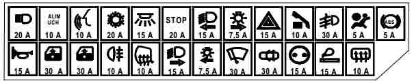
Circuit breakers
| 1 | (7.5A) Automatic transmission |
| 2 | – |
| 3 | (30A) Engine management |
| 4 | (5A / 15A) Automatic transmission |
| 5 | (30A) Brake servo vacuum pump relay (F4Rt) |
| 6 | (10A) Engine management |
| 7 | – |
| 8 | – |
| 9 | (20A) Air conditioning system |
| 10 | (20A / 30A) Anti-lock braking system / stability control system |
| 11 | (20A / 30A) Buzzer (s) |
| 12 | – |
| 13 | (70A) Coolant Heaters – If Equipped |
| 14 | (70A) Coolant Heaters – If Equipped |
| 15 | (60A) Cooling fan motor control |
| 16 | (40A) Headlamp washers, heated rear window, multifunction control module |
| 17 | (40A) Anti-lock braking system / stability control system |
| 18 | (70A) Combination switch, daylight system, multifunction control box |
| 19 | (70A) Heater / air conditioner, multifunction control unit |
| 20 | (60A) Battery current monitor relay (some models), combination switch (some models), daytime running lights, multifunction control box |
| 21 | (60A) Power seats, multifunction control module, fuse / relay box, center console, sunroof |
| 22 | (80A) Heated windshield (some models) |
| 23 | (60A) Windshield wiper, electric parking brake |
Relay type 1
- Coolant heater relay
- Cooling Fan Motor Relay (Without A / C, —01/03)
- Brake booster vacuum pump relay (F4 Rt)
- Brake servo vacuum pump relay
- Coolant Heater Relay 3 – (—01/03 if equipped)
- Fuel pump relay
- Crankcase ventilation heater relay (F4 Rt)
- Engine control relay
- Cooling fan motor relay 1 – (with air conditioning, —01 / 03)
- Cooling fan motor relay 2
- Coolant Heater Relay 2 – (—01/03 If Equipped)
Relay type 2
- Additional heating relay
- Water pump relay
- A / C blower motor relay
- –
- –
- Fuel pump relay
- Heater relay (fuel gas ventilation system)
- Injection blocking relay
- Reciprocating compressor relay
- A / C blower motor relay
- Additional heating relay 2
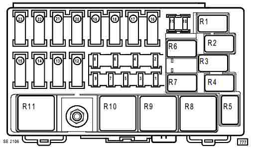
Passenger compartment
Box 1
Located at the top of the dashboard.

Photo

Diagram
Assignment
| F1 | – |
| F2 | (10A) Parking brake switch, ignition reader, multifunction control module, starter switch |
| F3 | (10A) Headlight range control unit, headlight range control unit (xenon headlights), windshield washer nozzle heaters, instrument cluster, voice synthesizer |
| F4 | (20A) Anti-theft system, automatic transmission (AT), central locking, heater / air conditioning system, rain sensor, interior air temperature sensor fan, interior rearview mirror, parking system, reversing lights, switch lights, windshield wiper motor |
| F5 | (15A) Interior lamps |
| F6 | (20A) Air conditioning, automatic transmission (AT), door lock, cruise control, diagnostic connector (DLC), power door mirrors, power windows, switch lights, brake lights, washers / wipers windshield |
| F7 | (15A) Headlamp leveling control module (xenon headlights), headlight range control, instrument cluster, LH headlamp – low beam |
| F8 | (7.5A) Right front dimensions |
| F9 | (15A) Direction indicators / hazard warning lights |
| F10 | (10A) Audio, power seats, power windows, instrument cluster, navigation, telematics |
| F11 | (30A) Air conditioning, fog lights, instrument cluster, voice synthesizer |
| F12 | (5A) SRS system |
| F13 | (5A) Anti-lock braking system (ABS) |
| F14 | (15A) Buzzer (s) |
| F15 | (30A) Driver’s door control module, power door mirrors, power windows |
| F16 | (30A) Passenger door control module, power windows |
| F17 | (10A) Rear fog lamps |
| F18 | (10A) Heated door mirrors |
| F19 | (15A) RH headlamp-low beam |
| F20 | (7.5A) Audio CD changer, instrument panel grille illumination, glove compartment illumination, instrument cluster rheostat, interior lamps, front left-hand dimensions, license plate lamps, navigation system, switch illumination |
| F21 | (30A) Rear window washer, high beam |
| F22 | (30A) Central locking |
| F23 | (15A) Accessory power connectors |
| F24 | (15A) Auxiliary equipment socket (rear), cigarette lighter |
| F25 | (10A) Brake light switch (brake pedal position sensor), heated rear window, steering column lock (some models) |
| F26 | – |
The fuse number 24 is responsible for the cigarette lighter.
Box 2
It is located behind the glove compartment on the passenger side.
Diagram

Designation
| 17 | Air conditioner relay |
| 2 | Power seat relay |
| 3 | Headlight washer pump relay |
| 4 | Brake light relay |
| 5 | Daytime lighting relay 1 |
| 6 | Daytime lighting relay 2 |
| 7 | Rear power window relay (some models) |
| F26 | (30A) Trailer socket |
| F27 | (30A) Luke |
| F28 | (30A) Power window regulator, rear left |
| F29 | (30A) Power window regulator, rear right |
| F30 | (5A) Steering wheel position sensor |
| F31 | (30A) Sunroof cover |
| F32 | – |
| F33 | – |
| F34 | (15A) Power seat – driver’s side |
| F35 | (20A) Heated front seats |
| F36 | (20A) Power seat – driver’s side |
| F37 | (20A) Power passenger seat |
Box 3
Located next to the CEBKS on the driver’s side
Diagram

Circuits protected
| 1 | Fog lamp relay |
| 2 | Relay 1 of the main ignition circuits |
| 3 | Rear wiper motor relay |
| 4 | Starter relay |
| 5 | Relay for auxiliary ignition circuits |
| 6 | Relay 2 main ignition circuits |
| 7 | Heated rear window relay |
| F1 | Power window shunt resistor – front |
| F2 | Power window shunt resistor – rear |
| F3 | Daytime Lighting Shunt Resistor – Headlights |
| F4 | Daylight bypass resistor – low beam |
In the cabin, under the glove box armrest mats, there is a fuse for disconnecting electricity consumers: 20A – Diagnostic connector, audio system, ECU, Central communication box, burglar alarm.

Also We have posted a video on our YouTube channel. Watch and subscribe.
If you have something to add, write in the comments.
Hello!
It’s a nice work from you to help others !
Please tell me where I find fuse for windshield washer pump on Renault Espace 4 2006 model ?
Thank you
Please help me to find fuse for heating/aircon control displays on all four doors Please ? I have shorted out the power to o/s rear door control owing to a careless door pad removal ! lost power to all 4 displays ?
Glenn. Did you find out where the fuse is located? My displays are dark after the floor above the climate unit under the car was soaked with water. Fan now lives it own life starting and stopping even the unit inside the plastic cover under the car seems completely dry.
Pour les commandes de clim Côté chauffeur derrière la manette frein de parking ( il faut démonté cet partie) bon travail
What about the battery (mega) fuses?
You are showing fuses for the phase 1 Renault Espace IV, mine is a 2009 2.0 dci Phase 2 and the fuses are different. Patr number for phase 1 is 8200447434 the phase 2 is 8200371619 unfortunately nobody has shown information for the 8200371619. Would be helpfull if you could list information.