The Jetour T2 was produced in 2023, 2024, 2025, 2026, 2027, 2028, and 2029. It is also known as the Jetour Traveller. In this post, we will describe the Jetour T2 fuses and relays, including fuse box diagrams, their locations, and photo examples. We will highlight the fuse responsible for the cigarette lighter.
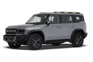
The purpose of fuses and relays may differ from those presented and depend on the year of manufacture, the level of electrical equipment and the region of delivery of your vehicle.
Passenger compartment
Inside the car, the fuse and relay box is located at the bottom of the instrument panel behind a plastic protective cover.
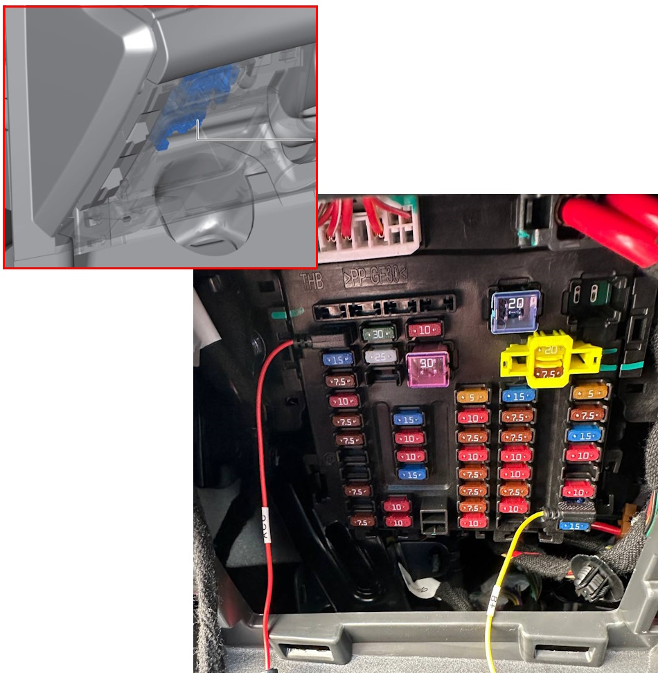
To access it, you need to remove the speaker cover (start with the two latches at the bottom) or remove the entire bottom panel.
Diagram
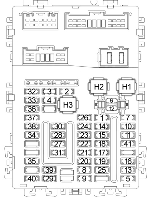
Assignment
| 1 | 15A Rear wiper relay |
| 2 | 10A Heated outside mirrors |
| 3 | 30A Heated rear window |
| 4 | 25A 220V inverter |
| 5 | 15A Reserve |
| 6 | 20A Automatic parking assist (APA), driver and front passenger footwell lamps |
| 7 | 5A Automatic parking assist (APA), ETC |
| 8 | 7.5A Driver and front passenger seat ventilation |
| 9 | 10A Heating and air conditioning system, instrument panel USB port, negative ion generator, ultraviolet emitter, PM2.5 sensor |
| 10 | 7.5A Ambient lighting, ambient light controller, rear microwave radars, rear collision warning radars, blind spot detection (BSD), driver and front passenger footwell lamps |
| 11 | 15A Audio/multimedia system |
| 12 | 7.5A Reserve |
| 13 | 20A Overhead control panel, interior lighting |
| 14 | 7.5A Diagnostic interface, IOV, system GLONASS, Telematics Box |
| 15 | 7.5A Automatic Transmission Control Unit (7DCT) |
| 16 | 10A Bluetooth Module, Low Configuration Logo Light |
| 17 | 10A Instrument Cluster, Central Display |
| 18 | 10A Reserve |
| 19 | 7.5A Rain Sensor, Body Control Module (BCM), Electronic Limited-Slip Differential, Torque Management System, Body Domain, Multi-Function Camera, Automatic Parking Assist (APA) |
| 20 | 7.5A Angle Sensor |
| 21 | 7.5A Diagnostic Interface, IOV, GLONASS System, Telematics Box |
| 22 | 10A Head Unit for Communication, Brake Fluid Level Sensor, Oil Pressure Switch, Driver and Front Passenger Seat Belt Warning |
| 23 | 7.5A Electric Power Steering (EPS) |
| 24 | 10A Electronic Gear Shift, Gear Display, Drive Mode Switch, Front Ford Radar, Second-Row Heated Seat Switch |
| 25 | 10A Engine Compartment Fuse and Relay Box |
| 26 | 5A Airbag Controller |
| 27 | 10A Roof Tent |
| 28 | 10A Body Control Module (BCM) |
| 29 | 10A Front USB |
| 30 | 15A Wireless Charging, Front Backup Power, Front Power Outlet |
| 31 | 15A Reserve |
| 32 | 15A Reserve |
| 33 | 15A Reserve |
| 34 | 7.5A Reserve |
| 35 | 7.5A Spiral Cable, Steering Wheel Vibration, Steering Wheel Heated |
| 36 | 7.5A 220V Inverter, ETC, Audio/Multimedia System, Inside Rearview Mirror |
| 37 | 10A Reserve |
| 38 | 7.5A Reserve |
| 39 | 10A Reserve |
| 40 | 7.5A Rear Backup Power |
| 41 | 10A Wireless Charging |
| Power fuses | |
| H1 | Reserve |
| H2 | 20A Power Tailgate |
| H3 | 30A Power Driver Seat, Power Front Passenger Seat |
| Relays | |
| R1 | Reserve |
| R2 | Rear Wiper Relay |
| R3 | Rear Window and Mirror Defogger Relay |
| R4 | Ignition Relay ACC1 |
| R5 | Ignition Relay ACC2 |
| R6 | Reserve |
| R7 | Ignition Relay IGN |
Fuse number 30, 15A, is responsible for the operation of the front cigarette lighter.
Engine compartment
Under the hood, in the engine compartment, the main block with fuses and relays is located on the left side, next to the battery and is covered with a protective cover.
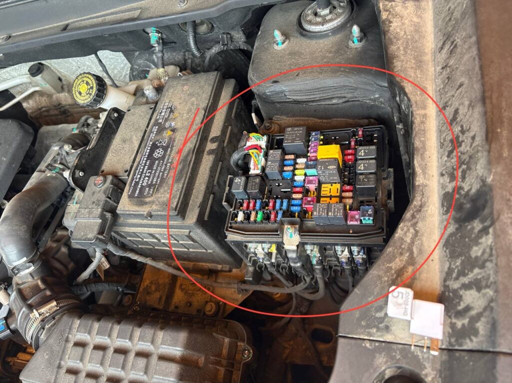
Check the information against your diagram on the back of the unit cover.
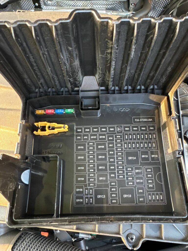
Diagram
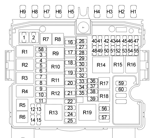
Description
| 1 | 40A Electronic Power Steering (ESP) Control Unit |
| 2 | 60A Automatic Transmission Control Unit (7DCT) |
| 3 | 5A Electronic Power Steering (ESP) Control Unit |
| 4 | 5A Brake Switch |
| 5 | 10A Engine Control Unit (ECU), Transmission Control Unit (TCU) |
| 6 | Spare |
| 7 | 7.5A Forward Radar Module (FRM), Front Microwave Radars |
| 8 | Spare |
| 9 | 7.5A Energy Saving Power Supply |
| 10 | 10A Right High Beam |
| 11 | 10A Left High Beam |
| 12 | 7.5A Interior Lighting, Interior Lighting |
| 13 | 10A Right Low Beam, Headlamp Range Adjustment |
| 14 | 10A Left Low Beam, Headlamp Range Adjustment |
| 15 | Spare |
| 16 | Spare |
| 17 | 60A Engine Cooling Fan |
| 18 | Spare |
| 19 | 30A Blower Relay |
| 20 | 40A Electronic Power Steering (ESP) Control Unit |
| 21 | 30A Starter Relay |
| 22 | 30A Overload Protection Window pinch protection, front left and rear right power windows |
| 23 | 30A Window pinch protection, front right and rear left power windows |
| 24 | 20A Torque management system |
| 25 | 20A Limited slip differential |
| 26 | 25A Rear backup power, rear power outlet |
| 27 | 15A Electronic vacuum pump |
| 28 | 15A Fuel pump |
| 29 | 5A Brake switch |
| 30 | 10A Air conditioning compressor |
| 31 | 25A Body control module, system power supply |
| 32 | 15A Heated seats |
| 33 | 25A Central locking, electric door mirrors, luggage compartment |
| 34 | 10A Main relay, engine control module, headlights, heater relay |
| 35 | 30A Lighting |
| 36 | 15A Horn |
| 37 | 5A Relay coil |
| 38 | 15A Heated steering wheel |
| 39 | 5A Feedback |
| 40 | 25A Steering column lock, windshield washer, rear window washer, fuel filler cap Tank |
| 41 | Spare |
| 42 | 30A Audio Amplifier |
| 43 | 30A Lighting Control Module, Turn Signals |
| 44 | 5A Electric Parking Brake (EPB), Automatic Transmission Control Module (7DCT), Front Corner Microwave Radar |
| 45 | Spare |
| 46 | 20A Right Domain Controller |
| 47 | 30A Front Windshield Wiper |
| 48 | 15A Engine Control Unit (ECU) |
| 49 | 15A Ignition Coils, Brake Switch, Engine Speed Sensor, Boost Pressure Sensor, Desorption Pressure Sensor, Inlet Pressure and Temperature Sensor, Knock Sensor |
| 50 | 10A Oxygen Sensor |
| 51 | 10A Pressure Relief Control Valve, Variable Oil Pump, Crankcase Ventilation Heater, Electronic Thermostat |
| 52 | 15A Variable Valve Timing Valve, Intake, Variable Valve Timing Valve, Exhaust, Fuel Evaporative Shutoff Valve |
| 53 | 10A Water Pump, Engine Cooling Fan |
| 54 | Spare |
| 55 | Spare |
| 56 | Spare |
| 57 | Spare |
| 58 | Spare |
| 59 | 30A Heated Windshield Glass |
| 60 | 30A Heated Windshield |
| 61 | 30A RV Controller, Vehicle Exterior Lighting |
| Power fuses | |
| H1 | Spare |
| H2 | 80A Electronic Power Steering (ESP) |
| H3 | Spare |
| H4 | Spare |
| H5 | 150A Alternator |
| H6 | Spare |
| H7 | 80A Instrument Cluster Fuse and Relay Box |
| H8 | 100A Instrument Cluster Fuse and Relay Box |
| H9 | Spare |
| Relays | |
| R1 | Reserve |
| R2 | Main Relay, Engine Control Module |
| R3 | High Beam Relay |
| R4 | Low Beam Relay |
| R5 | Windshield Heated Relay |
| R6 | Windshield Heated Relay |
| R7 | Heater Relay |
| R8 | Horn Relay |
| R9 | Rear Backup Power Relay |
| R10 | Reserve |
| R11 | Starter Relay |
| R12 | Engine Drive Chain Status Relay |
| R13 | Reserve |
| R14 | Reserve |
| R15 | Vacuum Pump Relay |
| R16 | Reserve |
| R17 | Fuel Pump Relay |
| R18 | A/C Compressor Relay |
| R19 | Heater Relay |
Fuse number 26 is responsible for the operation of the rear socket.
A high-power fuse block and intelligent battery charging system (5A) can be mounted on the positive terminal.
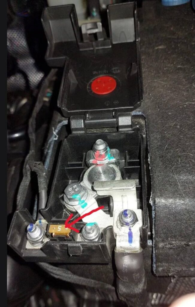
If you know a better this post, please write in the comments.
Hello, I need the complete electrical schematics for the Jetour T2, including the ECU and transmission wiring diagrams. Please note that I am willing to pay for this service if there is a fee.