Nissan Versa 1 generation was produced in 2004, 2005, 2006, 2007, 2008, 2009, 2010, 2011, 2012 and 2013 with coce C11. During this period, the car was restyled. We present for review information about the locations fuses and relays Nissan Versa 1G, we will show photo of the boxes and their diagrams with description. Let’s select the cigarette lighter fuse.

The purpose of the elements of your boxes and their meaning may differ from the one presented.
Contents
Passenger compartment
Fuse box is located in the dashboard, on the left behind the protective cover.

Check the assignment against your diagram on the back of the lid.
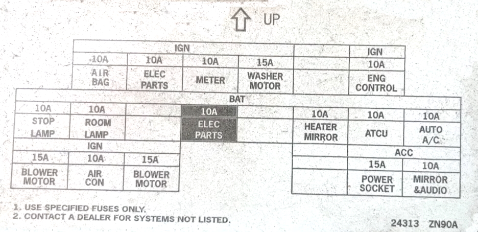
Diagram

Designation
Circuit breakers | |
| F1 | 10A SRC airbags |
| F2 | 10A Bodywork, Ignition Relay, Fuel Pump Relay, Body Electronics Module (BCM) |
| F3 | 10A warning indicators, warning buzzer, charging system |
| F4 | 15A Windscreen and tailgate washer pump |
| F5 | 15A Heated exterior mirrors |
| F6 | 10A Anti-theft system (NATS), Audio system |
| F7 | 10A Body electronics module (BCM) |
| F8 | 10A Central locking, remote control unit |
| F9 | 10A Brake lights, ABS, ESP, warning indicators |
| F10 | Reserve |
| F11 | Reserve |
| F12 | 10A Interior lighting, remote control unit, lighting, luggage compartment lighting, rain sensor |
| F13 | Reserve |
| F14 | 10A Instrument panel illumination, diagnostic connector (OBD II), intelligent car access system, direction indicators |
| F15 | 15A Electric fan heater |
| F16 | 10A Climatic unit |
| F17 | 15A Electric fan heater |
| F18 | 15A Rear socket |
| F19 | 10A Heated seats |
| F20 | 15A Front socket, cigarette lighter fuse |
Relay | |
| R11 | Heater fan relay |
| R12 | Interior auxiliary equipment relay |
For the front cigarette lighter, there is a 15A fuse number 20.
Engine compartment
Fuse and relay box
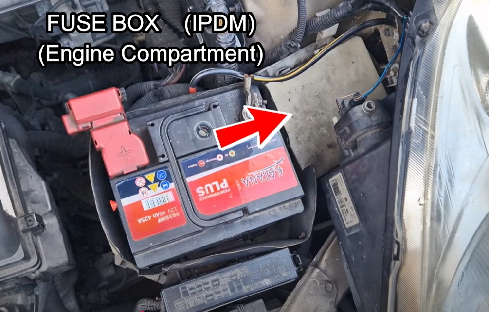
The photo
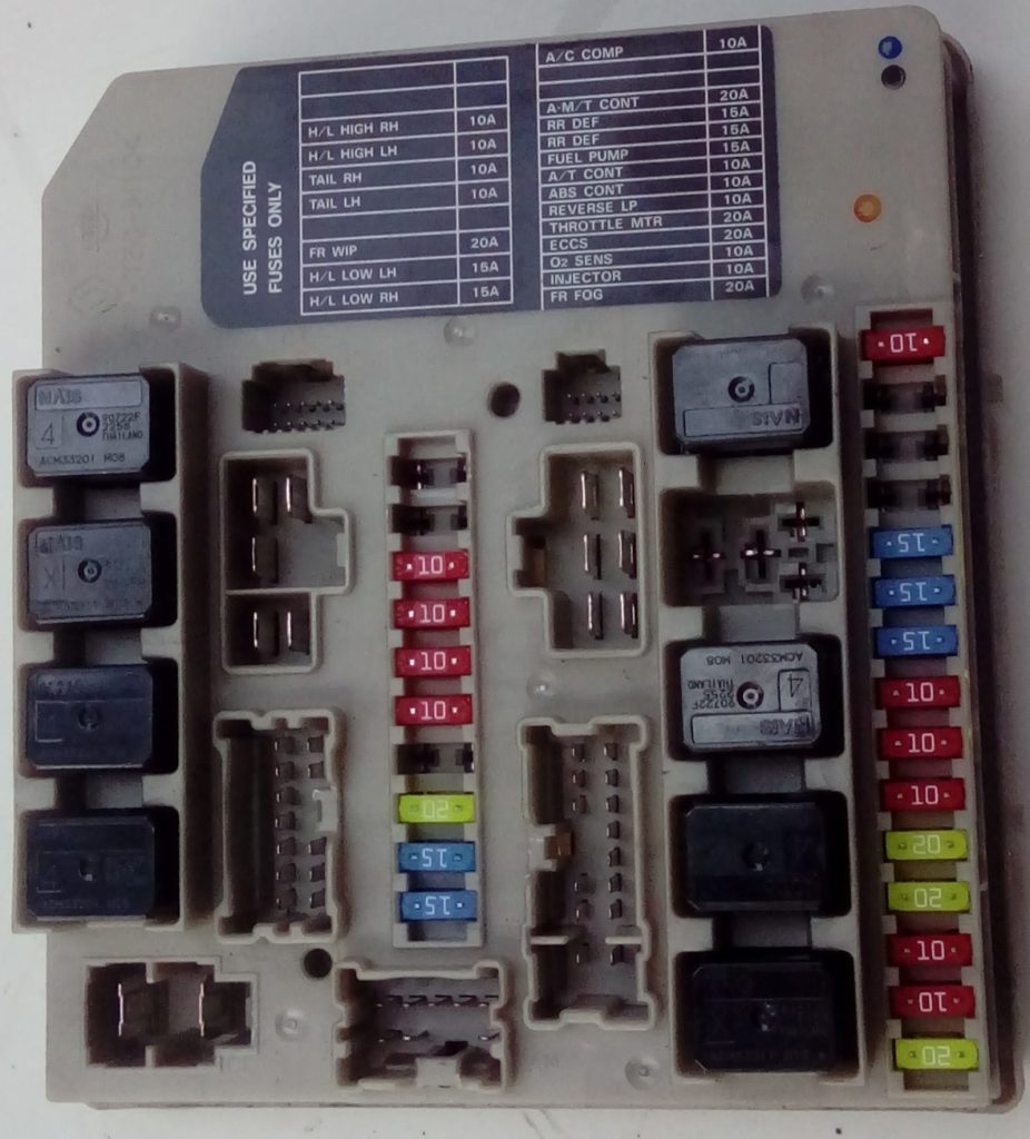
Diagram

Protected components
| Circuit breakers | |
| 41 | – |
| 42 | – |
| 43 | 10A High beam right, daytime running lights, automatic lighting system |
| 44 | 10A High beam left, daytime running lights, automatic lighting system |
| 45 | 10A Side light on the right side, automatic lighting system, backlight |
| 46 | 10A Side light on the left side, automatic lighting system, lights, headlights |
| 47 | – |
| 48 | 20A Windshield wiper and washer |
| 49 | 15A Low beam left, daytime running lights, automatic lighting system |
| 50 | 15A Low beam right, daytime running lights, automatic lighting system |
| 51 | 10A A / C compressor clutch |
| 52 | – |
| 53 | – |
| 54 | 20A Automatic transmission control unit |
| 55 | 15A Heated rear window, fuse No. 5 (heated mirrors) |
| 56 | 15A Heated rear window, fuse No. 5 (heated mirrors) |
| 57 | 15A Fuel pump relay |
| 58 | 10A Speed sensor (automatic transmission), oil temperature sensor (automatic transmission), automatic transmission control unit, turbine rotation sensor |
| 59 | 10А ABS, ESP |
| 60 | 10A Automatic transmission selector, starting system, reversing lamps, automatic transmission indicators, rear wiper and washer |
| 61 | 20A Throttle valve relay |
| 62 | 20A Engine control unit, MAF sensor, crankshaft position sensor, camshaft position sensor, canister purge valve, ignition system, intake valve, anti-theft system, injectors, fuel drive, turbine valve |
| 63 | 10A Fuel injection system, front heated oxygen sensor, rear heated oxygen sensor |
| 64 | 10A Fuel injection system |
| 65 | 20A Front fog light |
| Relay | |
| R1 | 1) Heated rear window, 2) Dipped beam |
| R2 | 1) Engine control unit (ECM), 2) Side light |
| R3 | 1) Low beam, 2) High beam left |
| R4 | 1) Front fog light, 2) High beam right |
| R5 | 1) Starter, 2) A / C compressor clutch |
| R6 | Front fog light |
| R7 | 1) Cooling fan (high speed), 2) Windshield wiper |
| R8 | 1) Cooling fan (low speed), 2) Cooling fan (high speed) |
| R9 | 1) Ignition, 2) Cooling fan (low speed) |
Fuse box
It is also located next to the battery.

Diagram from covery

Diagram
 Appointment
| 31 | – |
| 32 | – |
| 33 | – |
| 34 | 15A Audio system |
| 35 | 10A Sound signal |
| 36 | 10A charging system |
| 37 | 10A Daytime running lights |
| 38 | – |
| F | 40А ABS, ESP |
| G | 40A Cooling fan relay (high speed), cooling fan relay (low speed) |
| H | 40A Ignition lock |
| I | 40A Auxiliary heater (PTC) |
| J | 40A Windows, body electronics module (BCM) |
| K | 30А ABS, ESP |
| L | 30A Headlight cleaners |
| M | 60A Power steering |
| R1 | Daytime Running Lights |
| R2 | Sound signal |
Additional power fuse box

- N 80A – Auxiliary heater (PTC)
- O 60A – Glow plugs
- P 80A – Auxiliary heater (PTC)
Power fuse box
Located on the positive battery circuit.

- А – 80/140 / 250А – Charging system, starting system, fuses
- B – 80 / 100A – Fuses
- C – 80A – Fuses
- D – 60A – Ignition relay, fuses, fuel pump relay
- E – 80A – Auxiliary relay, fuses, heater relay
On our YouTube channel, we also posted a video. Watch and subscribe.
If you have anything to add, please write in the comments.
Where is starter relay located on 2009 Versa?
Where is/are the front power windows fuses located for the 2008 Nissan Versa