The first-generation Nissan Rogue was produced in 2007, 2008, 2009, 2010, 2011, 2012, 2013 with the model code S35. During this time, the model was updated. In this article, you can find information describing the fuses and relays in the Nissan Rogue 1G, including fuse box diagrams, their locations, and photo examples. We’ll highlight the cigarette lighter fuse.

The purpose of fuses and relays may differ from that described here and depends on the year of manufacture and the level of electrical equipment in your vehicle.
Contents
Passenger compartment
In the passenger compartment, the fuse box with fuses and relays is located at the bottom of the dashboard behind the glove compartment.
Photo for example
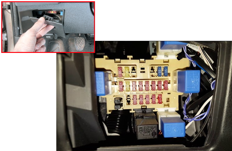
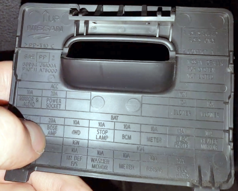
Check the actual description with yours on the back side of the protective cover.
Diagram
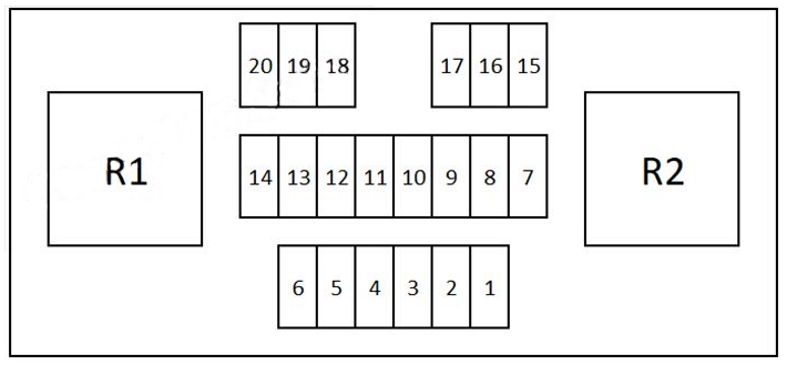
Assignment
| 1 | (Electric parts) Protects several circuits |
| 2 | (Air bag) Airbag |
| 3 | (Meter) Instrument cluster |
| 4 | (Washer motor) Windshield washer |
| 5 | (Rear Defroster) Rear defroster |
| 7 | (Heater Mirror) Mirror heater |
| 8 | (Electric parts) Protects several circuits |
| 9 | (Meter) Instrument cluster |
| 10 | (BCM) Body control module |
| 11 | (Stop Lamp) Stop lights |
| 12 | (4WD) All wheel drive system |
| 13 | (Bose amplifier) Audio system |
| 14 | (Intelligent key) Smart key system |
| 15 | (Blower motor) AC blower motor |
| 16 | (Blower motor) AC blower motor |
| 19 | (Power Socket) Cigar lighter / power outlet |
| 20 | (Mirror, Audio) Power control mirror; Audio system |
Fuse number 19 are responsible for the cigarette lighter.
Relay
- R1 – Ignition auxiliary circuits relay
- R2 – Heater blower relay
Engine compartment
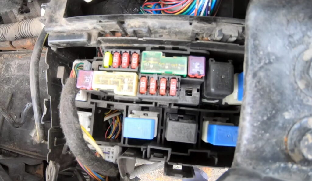
Under the hood, the fuse and relay boxes are located on the left side; to access them, you need to remove the air intake pipe.

Fuse box 1
Type 1
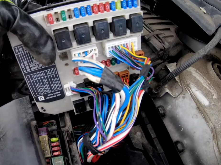
Photo

Diagram

Allocation
| 32 | – |
| 33 | – |
| 34 | 10A Headlamp High RH, Daytime Light System |
| 35 | 10A Headlamp High LH, Daytime Light System |
| 36 | 10A Parking Lamp, License Lamp, Tail Lamp, Illumination |
| 37 | 10A Parking Lamp, License Lamp, Tail Lamp |
| 38 | – |
| 39 | 30A Front Wiper Relay, Front Wiper High Relay |
| 40 | 15A Headlamp Low, Daytime Light System |
| 41 | 15A Headlamp Low, Daytime Light System |
| 42 | 10A A/C Relay |
| 43 | – |
| 44 | – |
| 45 | – |
| 46 | 15A Rear Window Defogger Relay |
| 47 | 15A Rear Window Defogger Relay |
| 48 | 15A Fuel Pump Relay |
| 49 | 10A Transmission Control Module (Power Supply), Secondary Pressure Sensor Solenoid Valve, CVT Indicator Lamp, Primary Speed Sensor CVT (Revolution Sensor) |
| 50 | 10A Anti-lock Brake System |
| 51 | 10A Heated Oxygen Sensor |
| 52 | 15A Throttle Control Motor Relay |
| 53 | 20A (ECCS) Air conditioning system |
| 54 | 10A Fuel Ignition System Function, Air Fuel Ratio Sensor |
| 55 | 10A Injector, Fuel Ignition System Function |
| 56 | 15A Front Fog Lamp |
| Relay | |
| R1 | Rear Window Defogger |
| R2 | Engine Control Module (ECM) |
| R3 | Headlamp Low |
| R4 | Front Fog Lamp |
| R5 | Starter |
| R6 | Cooling Fan 2 |
| R7 | Cooling Fan 3 |
| R8 | Cooling Fan 1 |
| R9 | Ignition |
Type 2
Diagram form the covery
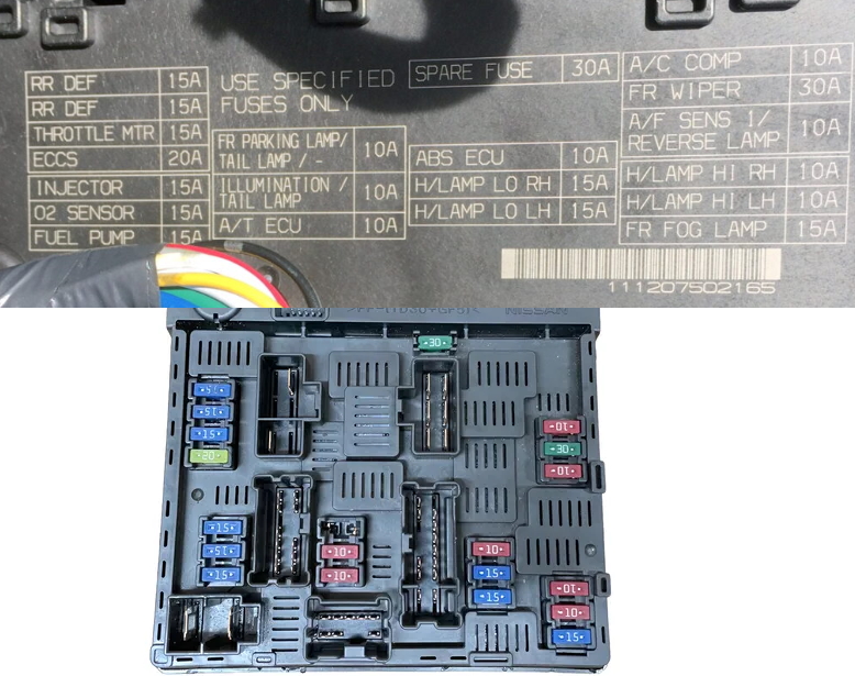
Designation
| Fuse | Function |
|---|---|
| RR DEF 15A | Rear defogger |
| RR DEF 15A | Rear defogger |
| THROTTLE MTR 15A | Throttle motor |
| ECCS 20A | Engine Control (ECCS) |
| INJECTOR 15A | Fuel injectors |
| O2 SENSOR 15A | Oxygen sensor |
| FUEL PUMP 15A | Fuel pump |
| FR PARKING LAMP / TAIL LAMP 10A | Front parking lamps / Tail lamps |
| ILLUMINATION / TAIL LAMP 10A | Illumination / Tail lamps |
| A/T ECU 10A | Automatic Transmission ECU |
| ABS ECU 10A | ABS control unit |
| H/LAMP LO RH 15A | Right headlamp low beam |
| H/LAMP LO LH 15A | Left headlamp low beam |
| A/C COMP 10A | Air conditioner compressor |
| FR WIPER 30A | Front windshield wiper |
| A/F SENS 1 / REVERSE LAMP 10A | Air-fuel ratio sensor 1 / Reverse lamps |
| H/LAMP HI RH 10A | Right headlamp high beam |
| H/LAMP HI LH 10A | Left headlamp high beam |
| FR FOG LAMP 15A | Front fog lamps |
| SPARE FUSE 30A | Spare fuse (unused) |
Fuse box 2

Diagram
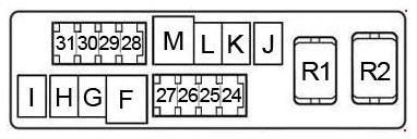
Appointment
| 24 | 20A Heater seat |
| 25 | 10A Horn, Remote Keyless Entry System, Intelligent Key System, Vehicle Security (Theft Warning) System, Charging System |
| 26 | 10A Daytime Light System |
| 27 | 10A Trailer |
| 28 | 10A Audio |
| 29 | 10A Woofer |
| 30 | 10A Anti-theft |
| 31 | 20A Audio, Vehicle Information and Integrated Switch System, Audio Visual Communication System |
| F | 60A Electronic Controlled Power Steering, EPS |
| G | 30A Anti-lock Brake System |
| H | 30A Anti-lock Brake System |
| I | – |
| J | 50A Low Tire Pressure Warning System, Sunroof, Power Door Lock, Daytime Light System, Front Fog Lamp, Turn Signal and Hazard Warning Lamps, Combination Switch, Parking Lamp, License Lamp, Tail Lamp, Warning Chime, Illumination, Remote Keyless Entry System, Intelligent Key System, Trunk Lid Opener, Hands Free Telephone, Vehicle Security (Theft Warning) System, Nissan Anti-Theft System, Power Window, Rear Window Defogger, Room/Map Lamps, Vanity Lamp, Luggage Lamp, Front Wiper and Washer, Vehicle Information and Integrated Switch System, Audio Visual Communication System Fuse: “9” |
| K | 40A Cooling Fan |
| L | 40A Cooling Fan |
| M | 40A Starting System, Ignition Switch |
| Relay | |
| R1 | Horn |
| R2 | Fan |
Fuse box 3
This block is attached to the positive terminal of the battery.
Diagram
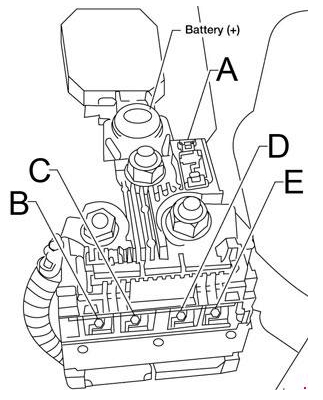
Description
| A | 225A Starting System, Charging System, Fuse: “E”, “D” |
| B | 80A Ignition Relay (Fuse: “48”, “49”, “50”, “51”, “54”, “55”) |
| C | 100A Front Blower Motor Relay (Fuse: “10”, “11”), Accessory Relay (Fuse: “5”, “6”, “7”), Fuse: “17”, “18”, “19”, “20”, “21”, “22” |
| D | 60A Front Fog Lamp Relay (Fuse: “56”), Headlamp Low Relay (Fuse: “40”, “41”) Headlamp High Relay RH, Headlamp High Relay LH, Tail Lamp Relay, Fuse: “39”, “42” |
| E | 100A Fuse: “25”, “26”, “27”, “28”, “30”, “31”, “F”, “G”, “H”, “J”, “K”, “L”, “M” |
On our YouTube channel, we also posted a video. Watch and subscribe.
If you know how to make the post better, write in the comments.