Nissan Maxima A35 represents the seventh generation of the Maxima model range, which was produced in 2009, 2010, 2011, 2012, 2013, and 2014. During this time, the model has got an update. In this post, you will find a description of the fuses and relays of the Maxima A35 with fuse box diagrams, their locations, and photo examples. Let’s highlight the cigarette lighter fuse.
The purpose of fuses and relays may differ from that described and depends on the year of manufacture and the level of electrical equipment in your vehicle.
Passenger compartment
In the passenger compartment, the fuse box with fuses and relays is located at the bottom of the dashboard behind the glove compartment.
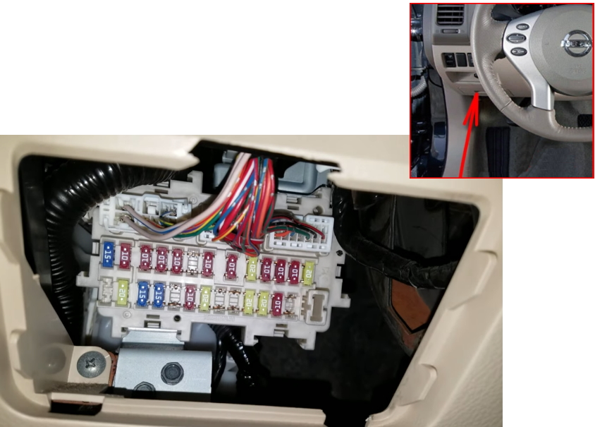
Check the assignment of the elements against your diagram on the back of the block cover.
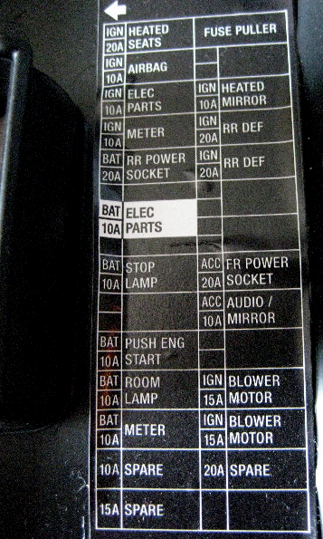
Example diagram from the covery
Diagram

Assignment
| 1 | 15A Heated front seats |
| 2 | 10A Airbags |
| 3 | 10A ASCD switch, Brake light switch, Headlight range control, Diagnostic socket, Air conditioning control unit, Steering wheel angle sensor, Body electronics control unit (BCM), Heated seat switch, Gas sensor, Ionizer, Rear curtain, Front seat ventilation switch, Rear seat ventilation switch, Seat ventilation unit, Engine mountings |
| 4 | 10A Back-up Lamp, Audio, Navigation, ABS, TCS, VDC, Charging System, CVT Control System, Engine Control System, Headlamp, Illumination, Combination Meter, SRS Air Bag Control System, Tire Pressure Monitoring System, Turn Signal and Hazard Warning Lamps, Warning Chime |
| 5 | 15/20A Power Socket (2007-2009: 15A; 2010-2013: 20A) |
| 6 | 10A Body Control Module, Intelligent Key System, Air Conditioner Control, CVT Control System, Engine Control System, Homelink Universal Transmitter |
| 7 | 10A Brake lights, Body Control Module (BCM) |
| 8 | Not used |
| 9 | 10A Interior Room Lamp, Body Control Module, Intelligent Key System, NVIS, Power Distribution System |
| 10 | 10A Seat Memory, Body Control Module (BCM) |
| 11 | 10A Headlamp, Intelligent Key System, Combination Meter, NVIS, Tire Pressure Monitoring System, Turn Signal and Hazard Warning Lamps, Vehicle Security System, Warning Chime, CVT Control System |
| 12 | Spare fuse |
| 13 | Spare fuse |
| 14 | Not used |
| 15 | 10A Heated mirrors, Air conditioning |
| 16 | 20A Rear Window Defogger |
| 17 | 20A Heated rear window |
| 18 | Not used |
| 19 | Not used |
| 20 | Cigarette lighter |
| 21 | 10A Audio system, Display, BOSE audio system, Body control module (BCM), Multifunction switch, DVD player, Mirror switch, AV module, Navigation unit, Camera, Rear passenger switch box, Air conditioning |
| 22 | – |
| 23 | 15A Heater relay |
| 24 | 15A Heater relay |
| 25 | Spare fuse |
| 26 | Not used |
The fuse number 20 and 5 is responsible for the lighter.
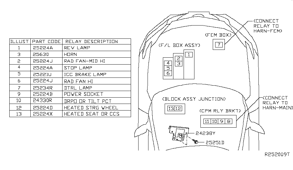
Relays
- R1 – Ignition relay
- R2 – Rear window heating relay
- R3 – Relay additional equipment
- R4 – Heater relay
Engine compartment
The two boxes with fuses and relays are located on the left side, under a protective cover.

The photo
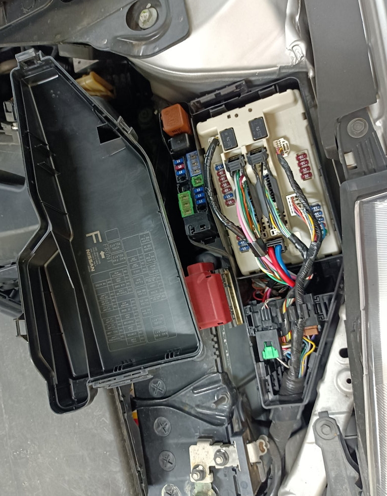
Diagram from the block cover

Fuse Box 1
Diagram

Designation
| 1 | 15A Fuel pump relay, Fuel pump with fuel level sensor |
| 2 | 10A Cooling fan relay 2,3, Transmission selector |
| 3 | 10A Speed sensor (primary, secondary), Transmission control unit |
| 4 | 10A Engine control unit, Injectors |
| 5 | 10A Yaw rate sensor, ABS |
| 6 | 15A Lambda Sensor, Heated Oxygen Sensor |
| 7 | 10A Washer pump |
| 8 | 10A Steering column |
| 9 | 10A A / C relay, A / C fan |
| 10 | 15A Ignition coils, Solenoid valve 1,2 of VIAS system, Solenoid valve for timing control system, Condenser, Engine control unit, Mass air flow sensor, Canister purge solenoid valve |
| 11 | 15A Engine control unit, Throttle valve |
| 12 | 10A Headlight range control, Front side lights |
| 13 | 10A Tail lights, Interior lighting, License plate light, Glove compartment lamp, Rear curtain switch (front / rear), Rear passenger switch box, Seat ventilation switch, Heated seat switch, Door handle lights, VDC switch, Headlight range control switch, Air conditioning, Trunk release button, Multi function switch, Combination switch, Hazard switch, Audio system, AV module, Backlight control, DVD player, Headlight range control, Navigation unit, Mirror switch |
| 14 | 10A High beam on the left side |
| 15 | 10A High beam on the right side |
| 16 | 15A Low beam on the left side |
| 17 | 15A Dipped beam on the right side |
| 18 | 15A Front fog lights |
| 19 | Not used |
| 20 | 30A Windshield wiper |
- R1 – Cooling fan relay 1
- R2 – Starter relay
Fuse Box 2
Diagram

Allocation
| 31 | 20A Optional connector |
| 32 | 15A Rear seat backrest control unit |
| 33 | 20A Socket relay |
| 34 | 20A Seat heating relay |
| 35 | 20A Audio system, front/rear display, navigation control unit, DVD player, camera control unit |
| 36 | 15A All-wheel drive |
| 37 | 10A Horn relay |
| 38 | 15A Generator, anti-theft system siren relay |
| F | 40A ABS |
| G | 40A ABS |
| H | – |
| I | 50A Ignition relay (fuses: “1”, “2”, ‘3’, “4”), IPDM E/R |
| J | 40A Automatic switch (trunk door control unit) |
| K | 40A Cooling system fan relay 2, cooling system fan relay 3 |
| L | 40A Body control module (BCM) circuit breaker (driver settings, driver’s seat power drive) |
| M | 40A Cooling system fan relay 1 |
| Relay | |
| R1 | Horn |
High power fuses
They are located on the positive terminal of the battery.
Diagram

Functions
- A – 250A Starter, Alternator, Fuse No. B, C
- B – 100A Engine compartment fuse box (no. 2)
- C – 60A Front fog lights, High beam relay, Low beam relay, Side light relay, Fuses: 18 – front fog lights, 20 – wiper (engine compartment fuse box (# 1))
- D – 100A Heater relay, Heated rear window relay, Fuses: 5, 6, 7, 9, 10, 11 (passenger compartment fuse box)
- E – 80A Ignition relay, Fuses: 8, 9, 10, 11 (engine compartment fuse box (# 1))
There is also a video on this topic on our YouTube channel. If you have anything to add, please write in the comments.