The Nissan Cube Z11 represents the second generation of the Cube model line, produced in 2002, 2003, 2004, 2005, 2006, 2007, and 2008. This publication describes the fuses and relays in the Nissan Cube Z11, with fuse box diagrams, their locations, and photographs. Note the fuse responsible for the cigarette lighter.
The assignment of fuses and relays may differ from those shown and depends on the year of manufacture and the level of electrical equipment in your vehicle.
Passenger compartment
In the interior of the vehicle, the fuse box is located at the bottom of the instrument panel, on the driver’s side, behind a protective cover.

Diagram

Designation
| 1 | Relay accessories |
| 2 | Heater blower motor relay |
| F1 | (15A) Windshield wiper |
| F2 | (10A) Instrument cluster indicators |
| F3 | (10A) SRS system |
| F4 | (10A) Multifunction control module 1, diagnostic socket |
| F5 | (10A) Brake light switch (brake pedal position sensor), ABS, brake lights |
| F6 | (10A) Central locking, anti-theft system, air conditioning system |
| F7 | (10A) Multifunction control module 1 |
| F8 | (10A) Indicators in instrument cluster, diagnostic connector (DLC) |
| F9 | (15A) Heater air conditioner |
| F10 | (15A) Heater air conditioner |
| F11 | (15A) Cigarette lighter fuse |
| F12 | (10A) Audio system, navigation system, anti-theft system, electric door mirrors, trip computer |
| F13 | (10A) Heated rear window |
| F14 | (10A) Daytime running lamps |
| F15 | (10A) Heated seats |
| F16 | (10A) Air conditioner |
| F17 | (10A) Anti-theft system, central locking, interior lamps |
The fuse number 11 at 15A is responsible for the cigarette lighter.
Engine compartment
In the engine compartment next to the battery there are two blocks with fuses and relays.
Fuse and Relay Box
The photo
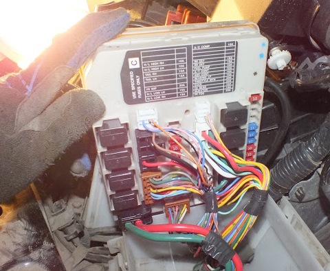
Check the fuse assignment with the diagrams on the protective cover or on the box itself.

Diagram

Designation
- 43 (10A) Front high beam headlamp, right
- 44 (10A) Front high beam headlamp, left
- 45 (10A) Air conditioner, standard music lights and right dimensions, lights, headlight adjustment motors
- 46 (10A) Parking lighting, lighting switches under. seats, door opening
- 48 (20A) Windshield wiper motor
- 49 (15A) Left low beam headlamp
- 50 (15A) Front low beam headlamp, right
- 51 (10A) Air conditioning compressor
- 55 (15A) Heated rear window
- 56 (15A) Heated rear window
- 57 (15A) Gasoline pump (CH)
- 58 (10A) Power supply for automatic transmission systems (AT)
- 59 (10A) ABS control unit
- 60 (10A) Additional electrical
- 61 (20A) To terminal B + IPDM, Throttle valve motor and relay (for CH)
- 62 (20A) To terminal B + IPDM, to the ECM / PW and BATT terminals of the ECM © block, the power supply terminal of the ignition coils, DPKV, DPRV, EVAP Canister valve, IVTC valve
- 63 (10A) Oxygen sensors
- 64 (10A) Injector coils, injection system
- 65 (20A) Front fog lights
- R1 – Rear window defogger relay
- R2 – Main relay of the engine control unit
- R3 – Relay low beam headlights
- R4 – High beam relay
- R5 – Starter relay
- R6 – Relay for fan 2 of the engine cooling system
- R7 – Relay for fan 1 of the engine cooling system
- R8 – Relay for fan 3 of the engine cooling system
- R9 – Ignition relay
Fuse Box
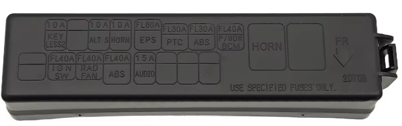
Diagram

Appointment
| 1 | 10A Immobilizer |
| 2 | 10A Heated seats |
| 3 | 10A Generator |
| 4 | 10A Buzzer |
| 5 | 60/30 / 30A Control unit for electric power steering, headlight washer glass, ABS system |
| 6 | 50A Electric drive glass lifters |
| 7 | Reserve |
| 8 | 15A Diesel injection system |
| 9 | 10A Throttle assembly |
| 10 | 15A Head unit of audio systems |
| 11 | 40/40 / 40A ABS system. body electrical control unit, ignition system |
| 12 | Reserve |
| R1 | Horn relay |
On our YouTube channel, we also posted a video. Watch and subscribe.