Mercedes W245 is a series of compact B-class cars of the German brand Mercedes-Benz, which was produced in 2005, 2006, 2007, 2008, 2009, 2010 and 2011 with the designation B160, B170, B180, B200. During this time, the model has been restyled. In this publication, we will provide information on the location of all electronic control units, a description of the fuses and relays Mercedes w245 with box diagrams and photo examples of their execution. Select the fuse responsible for the cigarette lighter.

The allocation of the fuses and relays may differ from the one shown and depends on the year of manufacture and the level of equipment of your car.
Contents
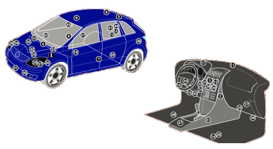
Location
Layout
Assignment
| 1 | ABS electronic control unit |
| 2 | Heater/A/C blower motor resistor – in heater box |
| 3 | A/C/Heater Control Unit – Behind A/C/Heater Control Panel |
| 4 | Air conditioning / heating humidity sensor – on the intake resonator |
| 5 | Antenna unit 1 – on the ceiling panel |
| 6 | Antenna unit 2 – on the ceiling panel |
| 7 | Side impact sensor, driver’s side – B-pillar |
| 8 | Side impact sensor, passenger side – B-pillar |
| 9 | Anti-theft control unit – behind the front interior lamp |
| 10 | Anti-theft siren – on intake resonator |
| 11 | Sunlight sensor |
| 12 | Audio System Amplifier – Behind Right Rear Side Trim Panel |
| 13 | Auxiliary heater control unit – in the air conditioning/heater control panel |
| 14 | Battery – legroom |
| 15 | CAN Data Bus, Gateway Control Unit, Audio – Behind Right Rear Side Trim Panel |
| 16 | CAN Data Bus, Gateway Control Unit – Behind Dashboard |
| 17 | Compass control unit – behind instrument cluster |
| 18 | Diagnostic connector (DLC) |
| 19 | Driver’s door electrical control unit – in the door |
| 20 | Electrical control unit of the left rear door – in the door |
| 21 | Control unit for electrical equipment of the right rear door – in the door |
| 22 | Passenger door electrical control unit – in the door |
| 23 | Electronic engine control unit-Diesel |
| 24 | Electronic engine control unit – gasoline |
| 25 | Fuse/Relay Box, Instrument Panel |
| 26 | Fuse/Relay Box, Footwell |
| 27 | Xenon headlight control unit, left – under the left headlight |
| 28 | Xenon headlight control unit, right – under the right headlight |
| 29 | Headlight range control motor, left |
| 30 | Headlight range control motor, right |
| 31 | Sound signal |
| 32 | Ignition lock control unit |
| 33 | Electronic immobilizer control unit – in the ignition switch control unit |
| 34 | Immobilizer ring antenna – ignition lock |
| 35 | Electronic control unit of the gas-cylinder power supply system |
| 36 | Multifunction Control Module – Functions: Low Brake Fluid Sensor, Central Locking, Coolant Level Sensor, Ambient Lights, Interior Lights, Alarm, Turn Signals, Rear Window Defroster, Horn, Reversing Light Switch, Tailgate Opener , windshield wiper/washer, rear window wiper/washer |
| 37 | multimedia control unit |
| 38 | Multifunction switch control unit |
| 39 | Navigation system control unit – in the audio system unit |
| 40 | Ambient temperature sensor – behind the bumper |
| 41 | Parking System Control Module – Behind Right Rear Side Trim Panel |
| 42 | Power steering control unit – on steering rack |
| 43 | Rain sensor – upper center windshield |
| 44 | Steering column electrical control unit – under the steering wheel |
| 45 | Steering column lock control unit – on the steering column |
| 46 | Subwoofer – Behind Left Rear Side Trim Panel |
| 47 | SRS electronic control unit – under the center console |
| 48 | Telephone interface control unit – under the seat |
| 49 | Trailer ECU – Behind Right Rear Side Trim Panel |
| 50 | Electronic gearbox control unit – in the gearbox |
| 51 | Gear shift control unit – selector |
Fuse box
The main fuse box is located next to the battery in the front passenger footwell. To access it, you need to remove the floor lining.

Diagram

Designation
| F1 | 10A Dorestyling: Brake light switch |
| 5A Facelift and restyle with code U58 (exterior lighting package): Brake light switch | |
| F2 | 25A Heated rear window |
| F3 | 7.5A Instrument cluster |
| EZS control unit | |
| F4 | 15A EZS control unit |
| Electric steering lock control unit | |
| F5 | 7.5A HAU control panel |
| Control panel KLA (automatic climate control) | |
| F6 | 15A Left horn |
| Right horn | |
| F7 | 25A Fuel pump with fuel level sensor |
| F8 | 25A Ceiling Control Panel |
| F9 | 40A ESP and BAS control unit |
| F10 | 40A Fan motor |
| F11 | 30A Engines 266: Relay el. terminal 87 circuits, motor |
| 40 Engines 640: Relay el. terminal 87 circuits, motor | |
| F12 | 5A Steering column electronic module |
| Multifunction steering wheel | |
| F13 | 25A Front left door control unit |
| F14 | 25A Front right door control unit |
| F15 | 25A ESP and BAS control unit |
| F16 | 10A Diagnostic connector |
| PTS control unit (parktronic, dorestyling) | |
| F17 | 5A Exterior lighting rotary switch |
| F18 | 7.5A Transmission 711, 716: Reverse signal switch |
| F19 | 5A Micromechanical angular rate sensor AY |
| F20 | 7.5A SRS control unit |
| F21 | 30A Starter |
| F22 | 7.5A Instrument cluster |
| F23 | 20A Engines 640 (from 1.9.08): Fuel filter condensation sensor with heating element |
| 7.5A Dorestyling: Heated washer nozzles | |
| F24 | 7.5A Electric power steering (ES) control unit |
| F25 | 7.5A Brake light switch |
| ESP and BAS control unit | |
| F26 | 7.5A Gearbox 722: Selector lever electronic module control unit |
| F27 | 10A Transmission 722: Electrical control module CVT (continuously variable automatic transmission) |
| F28 | 5A Exterior lighting rotary switch |
| F29 | 30A SAM control unit |
| F30 | 25A Relay el. circuit terminal 87F |
| F31 | 5A Exterior lighting rotary switch |
| Central interface control unit (vehicles before 11/30/05) | |
| F32 | 7.5A Engines 266: ME control unit |
| F33 | 15A Audio system |
| Audio module and navigation unit | |
| Block-panel for control and indication COMAND | |
| F34 | 25A Rear left door control unit |
| F35 | 25A Rear right door control unit |
| F36 | 10A Facelift: PTS control unit (Parktronic) |
| trailer control unit | |
| 7.5A Dorestyling: Trailer control unit | |
| Electrical connector mobile phone chain | |
| F37 | 7.5A SRS control unit |
| Passenger/Child Seat Recognition Sensor on the Front Passenger Seat | |
| Front passenger seat occupied recognition | |
| F38 | 25A Cigarette lighter, front |
| F39 | 25A Wiper motor |
| F40 | 25A Sectional roof: Overhead control box (sunroof motor) |
| 7.5A Ceiling control box | |
| F41 | 15A Tailgate wiper motor |
| F42 | 7.5A Glove box lighting with microswitch |
| Vanity mirror lighting left and right | |
| Pedal Depression Sensor (Driving School Package) | |
| Footwell light switch (driving school package) | |
| Detachable connection VICS+ETC power supply (Japan) | |
| Emergency call system control unit (USA) | |
| F43 | 7.5A Motors 266: Cable lug electr. circuit terminals 87M1e |
| 15A Motors 640: Cable lug electr. circuit terminals 87M1e | |
| Dual-fuel gas-petrol engine: Cable lug electr. circuit terminals 87M1e | |
| F44 | 15A Motors 266: Cable lug electr. circuit terminals 87M2e |
| 20A Motors 640: Cable lug electr. circuit terminals 87M2e | |
| F45 | 25A Engines 640: CDI system control unit |
| F46 | 25A Woofer (Japan, facelift) |
| 40A Speaker amplifier (restyling) | |
| 7.5A UHI control unit (universal mobile phone interface) (pre-styling) | |
| GSM network compensator 1800 (dorestyling) | |
| Phone control unit (Japan, doestyling) | |
| F47 | 7.5A Electrical connector mobile phone chain |
| UHI control unit (universal mobile phone interface) | |
| Voice control system control unit (dorestyling) | |
| Phone control unit (Japan, doestyling) | |
| F48 | 7.5A EDW control unit / towing protection / interior protection system |
| alarm siren | |
| F49 | 25A Upper control box |
| Front left seat cushion heating element (dorestyling) | |
| Element for heating the back of the front left seat (dorestyling) | |
| Front right seat cushion heating element (dorestyling) | |
| Front right seat back heating element (dorestyling) | |
| F50 | 7.5A Multimedia interface control unit (restyling) |
| Digital TV tuner (restyling) | |
| Control unit for digital sound broadcasting system (restyling) | |
| CD changer (dorestyling) | |
| Detachable connection VICS + ETC power supply (Japan, doestyling) | |
| 30A Service vehicles: Roof beam | |
| Cable lug electr. terminal 30 circuits | |
| F51 | 10A Passenger weight system (WSS) control unit (Canada) |
| Control panel for special signals (service vehicles) | |
| F52 | 7.5A Emergency call system control unit (ve/m up to 31.5.06) |
| 5A Power supply VICS+ETC connector (Japan, vehicles before 5/31/06) | |
| F53 | 30A Interior socket |
| Cigar lighter with ashtray light, rear | |
| F54 | 15A Service vehicles: Socket 2-pole 12V |
| 25A Speaker system amplifier (pre-styling) | |
| Woofer (dorestyling) | |
| F55 | 7.5A Dorestyling and restyling with code 614: |
| Front left headlight | |
| Front right headlight | |
| 10A Facelift: Front left headlight | |
| F56 | 10A Facelift: Front right headlight |
| F57 | 15A AHV drawbar connector, 13-pin (restyled) |
| 20A Audio interface control unit (Japan. pre-styling) | |
| 7.5A Emergency call system control unit | |
| SDAR control unit | |
| F58 | 25A Trailer control unit |
| F59 | 20A AHV drawbar connector, 13-pin |
| Trailer control unit (vehicles up to 31.5.05) | |
| F60 | 20A Driver’s seat contact strip |
| F61 | 20A Contact strip, front passenger seat |
| F62 | 40A Restyling: Relay el. terminal 15 circuits (2) (optional equipment: xenon headlights, mobile phone) |
| 25A Dorestyling: Relay el. terminal 15 circuits (2) (optional equipment: xenon headlights, mobile phone) | |
| F63 | 7.5A SDAR control unit (Canada) |
| 25A Roof beam (service vehicles) | |
| F64 | 40A Engines 266: Air pump relay |
| 80A Engines 640: End of glow plug time | |
| F65 | 80A Electric power steering (ES) control unit |
| F66 | 60A SAM control unit |
| F67 | 50A Relay el. terminal 15R circuits (2) (accessory) |
| F68 | 50A Standard equipment (facelift): Electric suction fan for engine and air conditioner with integrated regulator |
| 60A Special equipment (restyling): Dorestyling: (valid for engines 640.940, 640.941, 266.960, 266.980 and for engines 266.920, 266.940 with code (550): Drawbar)) | |
| F69 | 50A Relay el. circuit terminal 15R (1) |
| F70 | 60A Relay el. terminal 15 circuits (1) |
| F71 | 150A Engines 640: Additional PTC heater |
| F72 | 60A Dorestyling: Cable lug electr. terminal 30 circuits |
| Service vehicles: | |
| Fuse 7 (F7f7) | |
| Fuse 10 (F7f10) | |
| Taxi: | |
| Special vehicle multifunction control unit (MSS) |
Fuses 38 and 53 are responsible for the operation of the cigarette lighters.
Relay box
Under the instrument panel, at the feet of the front passenger, there is a block with a relay. You have to remove the trim to access it. The glove box does not need to be removed.

Diagram

Allocation
| Fuses | |
| 80 | 30A Taxi, company, rental cars: Special vehicle multifunction control unit (MSS) |
| 81 | 30A Taxi, company, rental cars: Special vehicle multifunction control unit (MSS) |
| 82 | 30A Taxi, company, rental cars: Special vehicle multifunction control unit (MSS) |
| 83 | 30A Taxi, company, rental cars: Special vehicle multifunction control unit (MSS) |
| Realy | |
| А | Relay el. circuit terminals 15R (2) |
| B | Relay el. circuit terminal 15R (1) |
| C | Horn relay |
| D | Heated rear window relay |
| E | Wiper relay, mode 1/2 |
| F | Wiper relay ON/OFF |
| G | Relay el. terminal 15 circuits (1) |
| H | Backup relay |
| I | Air pump relay |
| K | Fuel pump relay |
| L | Relay el. terminal 87 circuits, motor |
| М | Starter relay |
| N | Relay el. circuit terminal 87F |
| O | Relay el. terminal 15 circuits (2) |
Found a mistake or have something to add – write in the comments.