Infiniti JX35 and Infiniti QX60 model code L50 represents the first generation of the model range Infiniti QX60, which was produced in 2012 2013 2014 2015 2016 2017 2018 2019. During this time, the model has got a refresh. Here we’ll provide a description of the fuses and relays in the Infiniti QX60 JX35 1G with fuse box diagrams, their locations, and photo examples. Let’s highlight the cigarette lighter fuse.

The purpose of fuses and relays may differ from that described here and depends on the year of manufacture and the level of electrical equipment in your vehicle.
Contents
Passenger compartment
In the vehicle interior, the fuse box is located at the bottom of the instrument panel on the driver’s side.

Check the assignment of the elements against your diagram on the back of the protective covers.

Diagram

Assignment
| 1 | 10A Body Control Module (BCM), Warning System Switch, Auto Anti-Dazzling Inside Mirror, Auto Light System, Automatic Drive Positioner Back-Up Lamp, Daytime Light System, Drive Assistance System, Front Fog Lamp, Front Wiper and Washer System, Headlamp, Headlamp Aiming System, Homelink Universal Transceiver, Illumination, Inside Mirror, Intelligent Key System/Engine Start Function, Interior Room Lamp, IVIS, Moonroof System, Parking Lamps, License Plate Lamps, Tail Lamps, Power Door Lock System, Power Seats, Power Window System, Rear Window Defogger, Rear Wiper and Washer System, Tire Pressure Monitoring System, Trailer Tow, Turn Signal and Hazard Warning Lamps, Vehicle Security System, Warning Chime System, Seat Memory Switch |
| 2 | 15A Body Control Module (BCM) |
| 3 | 15A Body Control Module (BCM), Power Door Lock System, Intellgent Key System/Engine Start Function, Vehicle Security System |
| 4 | 15A Body Control Module (BCM), Power Door Lock System, Intellgent Key System/Engine Start Function, Vehicle Security System |
| 5 | Not Used |
| 6 | Not Used |
| 7 | Not Used |
| 8 | Not Used |
| 9 | 20A Rear Cargo Power Socket |
| 10 | 10A Stop Lamp Switch, Body Control Module (BCM), Intelligent Cruise Control (ICC) Brake Hold Relay, Engine Control Module (ECM) |
| 11 | 15A Bose Audio Amplifier |
| 12 | 15A Bose Audio Amplifier |
| 13 | 10A Combination Meter |
| 14 | 5A Air Conditioner Control, Drive Mode System, Heated Steering Wheel, Pre-Crash Seat Belt System, Rain Sensor |
| 15 | 15A Audio System, AV Control Unit, Display Unit, Satellite Radio Tuner, Bluetooth Control Unit, Video Distributor, Rear Auxiliary Input Jacks, Headrest Display Unit, Telematic Control Unit (TCU) |
| 16 | 5A Body Control Module (BCM) |
| 17 | 15A Front Blower Motor |
| 18 | Not Used |
| 19 | 20A Cigarette Lighter |
| 20 | 20A Rear Console Power Socket |
| 21 | 20A Front Console Power Socket |
| 22 | 10A Door Mirror Defogger |
| 23 | 15A Rear Window Defogger |
| 24 | 15A Rear Window Defogger |
| 25 | 10A Intelligent Key Warning Buzzer, Push-Button Ignition Switch, All-Wheel Drive (AWD) Control Module, Data Link Connector, Remote Keyless Entry Receiver, Seatback Power Return Control Unit, Transmission Control Module (TCM) |
| 26 | 5A Headlamp Aiming Switch |
| 27 | 15A Front Blower Motor |
| 28 | 15A 2nd Row Heated Seat |
| 29 | 5A Audio System, AV Control Unit, Around View Monitor Control Unit, Telematic Control Unit (TCU), Sonar Control Unit, Auto Anti-Dazzling Inside Mirror, Trailer Tow Relay №1, Trailer Tow Relay №2, Trailer Back-Up Relay, Heated Seat Relay, Climate Controlled Seat Relay |
| 30 | 10A Bluetooth Control Unit, Advanced Driver Assistance Systems (ADAS) Control Unit, Intelligent Cruise Control (ICC) Sensor, ICC Brake Hold Relay, Brake Pedal Position Switch, Engine Control Module (ECM), Warning Buzzer, Side Radar (LH/RH), Lane Camera Unit, Data Link Connector, Electronic Controlled Engine Mount Control Solenoid Valve, Air Conditioner Control, Ionizer, Exhaust Gas/Outside Odor Detecting Sensor, PTC Relay №1, PTC Relay №2, A/C 120V Outlet Main Switch, Power Seat |
| 31 | 5A Combination Meter |
| 32 | 10A Air Bag Diagnosis Sensor Unit, Occupant Classification System Control Unit |
| 33 | Not Used |
| 74 | 10A Heated Steering Relay |
Fuses numbered 19, 20 and 21 rated at 20A are responsible for the operation of the Cigarette Lighter and Power Socket.
There are several relays on the back of the unit.
Diagram

Decoding
- R1 Ignition 2
- R2 Electric fan motor
- R3 Rear window heater
- R4 Accessory 1
Additional relays

Engine compartment
In the engine compartment, under the hood, 4 blocks with fuses and relays can be installed.

Fuse box 1
Location

Photo – example of a block with a designation

Diagram
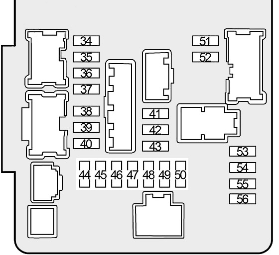
Allocation
| 34 | 10A Right Headlamp (High Beam) |
| 35 | 10A Left Headlamp (High Beam) |
| 36 | 15A Right Headlamp (Low Beam) |
| 37 | 15A Left Headlamp (Low Beam) |
| 38 | 10A Engine Control Module (ECM), VIAS Control Solenoid Valve, EVAP Canister Vent Control Valve, Throttle Control Motor Relay |
| 39 | 10A Engine Control Module (ECM), EVAP Canister Purge Volume Control Solenoid Valve, Intake Valve Timing Control Solenoid Valve, Intake Valve Timing Intermediate Lock Control Solenoid Valve, Exhaust Valve Timing Control Solenoid Valve, Mass Air Flow Sensor |
| 40 | 15A Heated Oxygen Sensors, Air Fuel Ratio Sensors |
| 41 | 30A Front Wiper Relay |
| 42 | 15A Front Fog Lamp Relay |
| 43 | 10A Daytime Running Light Relay |
| 44 | 15A Ignition Coils, Condenser, Engine Control Module (ECM) |
| 45 | 10A Fuel Injectors, Engine Control Module (ECM) |
| 46 | 10A Transmission Range Switch, Transmission Control Module (TCM), Primary Speed Sensor, Input Speed Sensor, Output Speed Sensor |
| 47 | 15A Fuel Pump Relay |
| 48 | 10A Cooling Fan Relay, Headlamp Aiming Motors, Headlamp Aiming Switch, Transmission Range Sensor |
| 49 | 10A All-Wheel Drive (AWD) Control Unit, Power Steering Control Module, ABS Solenoid Valve Relay, ABS Motor Relay, Steering Angle Sensor, Yaw Rate/Side/Decel G Sensor |
| 50 | 10A Front and Rear Washer System, Combination Switch |
| 51 | 10A Tail Lamps, License Plate Lamps, Trailer Tow Relay No.1, Headlamp Aiming Switch, Glove Box Lamp, Illumination |
| 52 | 10A Parking Lamps, Side Marker Lamps |
| 53 | 10A A/C Relay |
| 54 | Not Used |
| 55 | 15A Throttle Control Motor Relay |
| 56 | 10A Engine Control Module (ECM) |
Fuse box 2

Example of a diagram from the block cover

Diagram

Appointment
| 57 | 10A Alternator, Anti-Theft Horn Relay |
| 58 | 10A BOSE Audio System |
| 59 | 30A PTC Relay №1 (PTC Heater) |
| 60 | 30A PTC Relay №2 (PTC Heater) |
| 61 | 30ATrailer Tow Relay №2 (Trailer Receptacle) |
| 62 | 10A All-Wheel Drive (AWD) Control Unit |
| 63 | 15A Horn Relay, Intelligent Key System |
| 64 | 30A Seatback Power Return Control Unit |
| 65 | 10A Accessory Relay №2 (AV Control Module, Satellite Radio Tuner, A/C and AV Switch Assembly, Bluetooth Control Unit, Power Seat, Around View Monitor Control Unit, Video Distributor, Rear Auxiliary Input Jacks, Telematic Control Unit (TCU), Telematics Switch, Power Mirror Remote Control Switch, Combination Meter) |
| 66 | 15A Climate Controlled Seat, Heated Seat (Passenger Side) |
| 67 | 10A Trailer Tow Relay №1 (Trailer Receptacle) |
| 68 | 15AClimate Controlled Seat, Heated Seat (Driver Side) |
| 69 | 30A Inverter System |
| 70 | 20A Rear Blower Motor Relay |
| 71 | 20A Rear Blower Motor Relay |
| G | 30A Electric Brake (Trailer) |
| H | 60A Cooling Fan Relay |
| I | 50A ABS (Motor Relay) |
| J | 30A ABS (Solenoid Valve Relay) |
| K | 40A Ignition Relay №2 (Fuses: 28, 29, 30, 31, 32), Starter Relay, Starter Control Relay |
| L | 30A Pre-Crash Seat Belt System (Driver Side) |
| M | 30A Pre-Crash Seat Belt System (Passenger Side) |
| N | 40A Automatic Back Door System |
| O | 40A Body Control Module (BCM), Auto Light System, Automatic Back Door System, Back-Up Lamp, CVT Shift Lock System, Daytime Light System, Front Fog Lamp, Front Wiper and Washer System, Headlamp, Headlamp Aiming System, Heated Steering Wheel, Illumination, Intelligent Key System/Engine Start Function, Intelligent Key System, Interior Room Lamp, IVIS, Moonroof System, Parking Lamps, License Plate Lamps, Tail Lamps, Power Door Lock System, Power Seats, Power Window System, Rear Window Defogger, Rear Wiper and Washer System, Tire Pressure Monitoring System, Trailer Tow, Turn Signal and Hazard Warning Lamps, Vehicle Security System, Warning Chime System, Automatic Drive Positioner, Tilt & Telescopic Steering Column |
| P | Not Used |
| R1 | Horn Relay |
| R2 | Cooling Fan Relay |
Relay box 1
Diagram

Assignment
| 72 | 10A Trailer Back-Up Relay |
| 73 | 15A Trailer Tow Turn Relay (Left), Trailer Tow Turn Relay (Right) |
| 74 | 10A Heated Steering Relay |
| Relay | |
| R1 | PTC №2 |
| R2 | Intelligent Cruise Control (ICC) Brake Hold |
| R3 | Accessory №2 |
| R4 | Not Used |
| R5 | PTC №1 |
Relay box 2
Diagram

Designation
- 75 10A Driver Assistance System
- R1 Not Used
- R2 Not Used
- R3 Not Used
- R4 Daytime Running Light Relay
Power fuse box
A high-power fuse block in the form of fuse links is installed on the positive terminal of the battery.
Diagram

Description
| A | 250A Generator, Starter, Fuses: B, C, D |
| B | 100A Fuses: 57, 58, 59, 60, 61, 62, 63, 64, 72, 73, H, I, J, K, L, M, N, O |
| C | 80A Headlamp High Relay (Fuses: 34, 35), Headlamp Low Relay (Fuses: 36, 37), Tail Lamp Relay (Fuses: 51, 52), Fuses: 41, 42, 43, 68, 69, 70, 71 |
| D | 100A Power Steering Control Module |
| E | 80A Engine Control Module Relay (Fuses: 38, 39, 40), Ignition Relay No.1 (Fuses: 44, 45, 46, 47, 48, 49, 50) Fuses: 53, 55, 56 |
| F | 100A Accessory Relay No.1 (Fuses: 19, 20, 21), Rear Window Defogger Relay (Fuses: 22, 23, 24), Blower Motor Relay (Fuses: 17, 27), Fuses: 1, 2, 3, 4, 9, 10, 11, 12, 13, 14, 15, 16, 25, 65, 66, 67, G |
We also have a video on this topic on our channel. Watch and subscribe.
If you have anything to add, please write in the comments.
Can any please tell me what fuse is the outside front door handle light (courtesy lights) connected to?