The Hyundai i20 subcompact hatchback has been produced from 2008 to the present in 2 generations. The first generation was produced in 2009, 2010, 2011, 2012, 2013 and 2014. During this time, the model has been restyled. Since 2015, the 2nd generation of the Hyundai i20 has been on sale in 2016, 2017, 2018, 2019, 2020. In this post you will find a description of the fuses and relays of the Hyundai i20 with box diagrams and their locations. Note the cigarette lighter fuse.

The locations of the boxes for the 1st and 2nd generation are the same. There may be a difference in the design and purpose of the elements of the fuse boxes and relays. Check with your diagrams on the back of the protective cover.
Contents
Passenger compartment
Fuse box is located at the bottom of the dashboard.

Photo for example

Type 1
An example of a circuit from the covery.

or

Designation
| P / WDW -LH | Main switch for electric glass lifts, automatic blocking of electric drive glass driver’s door lifter glass, right rear door glass lifter control switch, front passenger door glass lifter control switch (for right-hand drive cars) |
| S/HTD | Front passenger seat heating switch, driver’s seat heating switch |
| RR WIPER | Rear window wiper motor, multi-function switch (wiper control switch) |
| H/LP RH | Headlight right, dashboard (headlights on) |
| IGN 2 | Headlight range control switch, passenger compartment temperature sensor, body electronic control module (BCM), air conditioning control module, sunroof control module, left / right headlights, fuse box and engine compartment relay (fuel filter heating relay (FFHS ), Daytime Running Light Relay (DRL), Blower Relay), Diesel Fuse / Relay Box (PTC 2 Heater Relay, PTC 3 Heater Relay) |
| PCU | Fuel filter warning sensor, air flow sensor, engine control module (ECM) (with manual transmission), powertrain control module (PCM) (with automatic transmission) |
| STOP LP | Brake Light Switch, Data Link Connector (DLC), Power Window Relay |
| A/BAG | Seat Belt Not Fastened Sensor Module, SRS Control Module |
| HAZARD | Alarm switch, alarm relay |
| SAFETY P/W | Automatic blocking block of the electric drive glass of the driver’s door lift |
| CLUSTER | On-board computer, instrument panel (backlight), body electronic control module (BCM) |
| TCU | Overdrive switch, pulse generator “A”, pulse generator “B”, vehicle speed sensor |
| IGN1 | Alternator (KAPPA), Electric Power Steering (EPS) Control Unit, Tire Pressure Monitor |
| SECTION | Electronic Stability Program (ESP) switch, steering angle sensor, anti-lock braking system (ABS) control unit, ESP control unit, yaw rate sensor, engine compartment fuse and relay box (multipurpose test connector) |
| IGN COIL | Ignition coil (KAPPA), ignition coils No. 1 – 4 (GAMMA), capacitor (GAMMA) |
| B/UP LP | Transmission mode switch (GAMMA), reversing lamp switch |
| A/BAG IND | Instrument panel (airbag lighting) |
| T/SIG LP | Alarm switch |
| TAIL LP LH | Daytime Running Light Relay (DRL), License Plate Lamp, LH Tail Combination Lamp, LH Headlight |
| TAIL LP RH | Headlight right, right rear combination lamp, lighting |
| ACC | Electric drive of outside rear-view mirrors, audio system, on-board computer |
| C/LIGHT | Cigarette lighter |
| RR FOG LP | Rear fog lamp relay |
| B/A HORN | Anti-theft alarm relay |
| DR LOCK | Tailgate unlock relay, door lock / unlock relay, full door lock relay |
| FRT FOG LP | Front fog lamp relay |
| FOLDING | Electric door mirrors control switch |
| S/ ROOF | Sunroof control unit |
| START | Engine control module (ECM) (for vehicles with diesel engine), fuse box and engine compartment relay (starter relay, anti-theft alarm relay) |
The cigarette lighter fuse in the diagram is designated as C / LIGHT or POWER OUTLET.
Type 2

Diagram
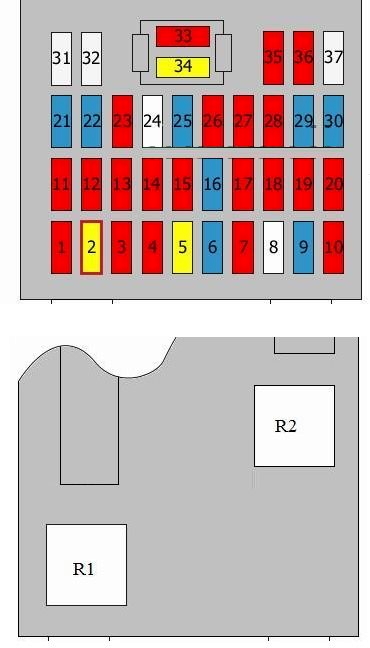
Assignment
| R1 | Rear heater relay |
| R2 | Power window relay |
| R3 | Front fog light relay |
| R4 | Rear fog light relay |
| R5 | Empty |
| R6 | Door unlock relay / Door lock relay |
| R7 | Tailgate unlocking relay / Tailgate lock relay |
| R8 | Tail light relay |
| R9 | Daylight running system relay |
| R10 | Hazard warning light relay |
| 1 | 10A Fuse and relay box in engine compartment (relays R7, R8), Engine control unit or not used |
| 2 | 20A Sunroof control unit |
| 3 | 10A Folding/ unfolding function of exterior mirrors |
| 4 | 10A Front fog light relay |
| 5 | 20A Door lock relay, door lock relay, door unlock relay, tailgate unlock relay |
| 6 | 15A Relay of the alarm system |
| 7 | 10A Rear fog light relay |
| 8 | 25A Not used |
| 9 | 15A Cigarette lighter fuse |
| 10 | 10A Audio, Trip computer, Electric mirrors |
| 11 | 10A Lighting, right headlamp, rear combination lamp(s) |
| 12 | 10A License plate light, Rear left combination light, Left headlight, Daylight running system relay |
| 13 | 10A Hazard warning switch |
| 14 | 10A Instrument panel |
| 15 | 10A Rear light switch, transmission range selector switch |
| 16 | 15A Condenser, Ignition coils 1 – 4 |
| 17 | 10A Fuse and relay box in engine compartment (diagnostic connector), ESP control unit, Electronic stability program (ESP) switch, Steering angle sensor, Yaw rate sensor, ABS control unit |
| 18 | 10A EPS Control Unit, Tire Pressure Monitoring System Control Unit, Generator |
| 19 | 10A Pulse generator, Vehicle speed sensor, Overdrive main switch |
| 20 | 10A Instrument panel, trip computer, body control module (BCM) |
| 21 | 15A Driver’s power window |
| 22 | 15A Hazard warning light relay, Hazard warning switch |
| 23 | 10A SRS control unit, Seat belt switch |
| 24 | 25A Not used |
| 25 | 15A Data link connector, Power window relay, Brake light switch |
| 26 | 10A Mass air flow meter, engine control unit, powertrain control module (PCM), fuel filter warning |
| 27 | 10A Fuse box No. 1 in engine compartment, relays R2, R3, Fuse and relay box in engine compartment, relays R2, R3, R5, Air-conditioning control unit, Headlights, Sunroof control unit, Body control unit (BCM), In-car temperature sensor, Headlight levelling switch |
| 28 | 10A Instrument panel, Right headlight |
| 29 | 15A Multifunction switch, Rear wiper motor |
| 30 | 15A Heated front seat(s) switch |
| 31 | 25A Driver’s power window, Rear left power window switch, Passenger power window switch (right-hand drive), Power windows, main switch |
| 32 | 25A Driver’s power window, Switch, rear right power window(s), Passenger’s power window switch (left-hand drive), Power windows, main switch |
| 33 | 10A Open door, instrument panel, trip computer, air conditioner control unit, luggage compartment lighting, overhead console, front interior lamps, interior lighting, rear heater relay, tire pressure monitoring system control unit, body control module (BCM) |
| 34 | 20A Audio |
| 35 | 10A Left headlight |
| 36 | 10A Powertrain control unit (PCM), Air-conditioning control unit, Electric mirrors, Engine control unit |
| 37 | 25A Multifunction switch, Front wiper motor |
Engine compartment
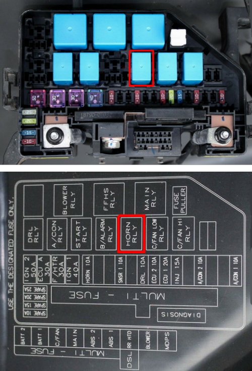
Type 1
Main fuse box
Located on the left side of the engine compartment, next to the battery.

Photo

Diagram

Appointment
| WATT 2 | Instrument panel junction box (relay for electric drive glass lifters, fuses (SAFETY P / W – 15 A, HAZARD – 15 A)) |
| WATT 1 | Instrument Panel Junction Box (Tail Lamp Relays, Fuses (S / ROOF – 20 A, FOLDING – 10 A, DR LOCK – 20 A, STOP LP – 15 A, B / A HORN – 15 A, RR FOG LP – 10 A , FRT FOG LP – 10 A, power connector (ROOM – 10 A, AUDIO – 20 A)) |
| C/FAN | High speed cooling fan relay, low speed cooling fan relay |
| MAIN | Generator, fuses (ABS 1 – 40 A. ABS 2 – 40 A, RR HTD – 40 A, BLOWER – 40 A, MDPS – 80 A, A / CON 1 – 10 A) |
| ABS2 | Multipurpose test connector, anti-lock braking system (ABS) control unit, electronic stability control (ESP) control unit |
| ABS 1 | Multipurpose test connector, anti-lock braking system (ABS) control unit, electronic stability control (ESP) control unit |
| RR HTD | Rear heating relay |
| BLOWER | Fan relay |
| MDPS | Electronic stability control (ESP) control unit |
| IGN 2 | Ignition |
| ECU A | Engine control unit (ECM) (with manual transmission), transmission control unit (PCM) (with automatic transmission), engine control relay (main relay) |
| F/PUMP | Fuel pump relay |
| IGN 1 | Egnition lock |
| HORN | Horn relay |
| SNSR 1 | Camshaft position sensor, fuel vapor storage purge control solenoid valve, oxygen sensor (upstream, downstream), immobilizer control unit, low speed cooling fan relay, high speed cooling fan relay |
| ECU B | Engine control unit (ECM) (with manual transmission), transmission control unit (PCM) (with automatic transmission) |
| DRL | Grounding (Body Electronic Systems (BCM) Control Unit) |
| ECU 1 | Engine control unit (ECM) (with manual transmission), transmission control unit (PCM) (with automatic transmission) |
| INJ | Injectors 1-4, idle speed control actuator, air conditioning relay, oil flow control valve (GAMMA) |
| A/CON2 | Air conditioner control unit |
| A / CON 1 | Air conditioner relay |
Additional box
Installed on the right side of the engine compartment on i20 diesel models.

There may be elements responsible for the operation of the engine, such as:
- GLOW – Glow plug relay, air heater relay
- PTC – Additional heater relay
Type 2
Diagram

Decoding
| 1 | Empty |
| 2 | Empty |
| 3 | 50A Ignition switch |
| 4 | 30A Engine control relay |
| 5 | 30A Fuel filter heater relay |
| 6 | 40A Ignition switch |
| 7 | 10A Horn relay |
| 8 | Empty |
| 9 | Empty |
| 10 | 10A Oxygen sensor, Brake light switch, Air heater, Cooling fan, low speed relay / Cooling fan, high speed relay |
| 11 | Empty |
| 12 | 10A Ground |
| 13 | 10A Fuel pressure regulator |
| 14 | 20A Engine control unit |
| 15 | 15A EGR, immobilizer control unit, engine compartment fuse and relay box, relays R1, R4, air conditioning relay, variable geometry turbine (VGT), camshaft position sensor |
| 16 | Empty |
| 17 | 10A Air-conditioning control unit |
| 18 | Empty |
| 19 | Empty |
| 20 | 10A Air-conditioning relay |
| 21 | 50A Fuse and relay box in passenger compartment, relay R2 and fuses 21, 22 |
| 22 | 50A Fuse and relay box in passenger compartment, relay R8 and fuses 2 – 7, 25, 33, 34 |
| 23 | 30A Cooling fan, high-speed relay / Cooling fan, low-speed relay |
| 24 | 125A Fuse and relay box in engine compartment, fuses 20, 25 – 29, 34, Generator |
| 25 | 40A ESP control unit, Multi-purpose check connector, ABS control unit |
| 26 | 40A ESP control unit, Multi-purpose check connector, ABS control unit |
| 27 | 40A Rear heater relay |
| 28 | 40A Blower relay |
| 29 | 80A EPS control unit |
| 30 | 25A Spare |
| 31 | 20A Spare |
| 32 | 15A Spare |
| 33 | 10A Spare |
| 34 | 150A Fuse and relay box No. 1 in engine compartment, relays R1 – R4 |
| R1 | Empty |
| R2 | Blower relay |
| R3 | Fuel filter heater |
| R4 | Engine control unit |
| R5 | Daylight running system relay |
| R6 | Air-conditioning relay |
| R7 | Starter relay |
| R8 | Security alarm system relay |
| R9 | Horn relay |
| R10 | Cooling fan, low-speed relay |
| R11 | Cooling fan, high-speed relay |
On our YouTube channel, we also posted a video. Watch and subscribe.
That’s all. And if you have something to add to the post, write in the comments.
flasher relay location in 2011 hyundai i20
Where is the parking/position light located?