The Honda Grace hybrid was produced in 2014, 2015, 2016, 2017, 2018, 2019, and 2020. During this time, the model received an update. In this article, you will find a description of the Honda Grace fuses and relays, along with block diagrams, their locations, and photo examples. We will highlight the fuse responsible for the cigarette lighter.

The purpose of the fuses and relays and their location may differ from those shown and depend on the year of manufacture, the level of electrical equipment and the region where your car was delivered.
Contents
Passenger compartment
Two fuse and relay boxes can be installed in the cabin, they are located under the instrument panel on the driver’s side.

Main box

Photo – example

Check the information with your diagrams under the steering wheel.
Label with designation

Assignment
| 1 | 20A Door lock |
| 2 | – |
| 3 | 10A Smart (Optional) |
| 4 | 15A Driver side door unlock |
| 5 | 15A Passenger side door unlock |
| 6 | 10A Driver’s door unlock |
| 7 | 10A Driver door lock |
| 8 | 20A Driver’s power window |
| 9 | 20A Passenger power window |
| 10 | 20A Rear left power window |
| 11 | 20A Rear right power window |
| 12 | 15A Door lock lock on the driver’s side |
| 13 | 15A Passenger’s door lock lock |
| 14 | – |
| 15 | 10A High beam right headlight |
| 16 | 7.5A STS (optional) |
| 17 | 20A ACC connector (console) (optional) |
| 18 | 20A Moonroof (optional) |
| 19 | 20A Front seat heater (optional) |
| 20 | – |
| 21 | – |
| 22 | 15A Washer |
| 23 | 10A Rear wiper |
| 24 | 7.5A Air conditioner |
| 25 | 7.5A Daytime running lights |
| 26 | 7.5A Starter Cut |
| 27 | 7.5A ABS/VSA |
| 28 | 10A SRS |
| 29 | 10A High beam left headlight |
| 30 | 10A ACG |
| 31 | 10A Power window |
| 32 | 15A Fuel pump |
| 33 | 7.5A SRS |
| 34 | 7.5A Instruments |
| 35 | 7.5A Mission SOL |
| 36 | 20A Front ACC connector |
| 37 | 7.5A ACC |
| 38 | 7.5A ACC key lock |
| 39 | 10A Option |
| 40 | 10A Rear wiper |
| 41 | — |
| 42 | — |
Relay

Description
| R1 | PGM-FI Main Relay 2 |
| R2 | Horn Relay |
| R3 | Power Window Relay |
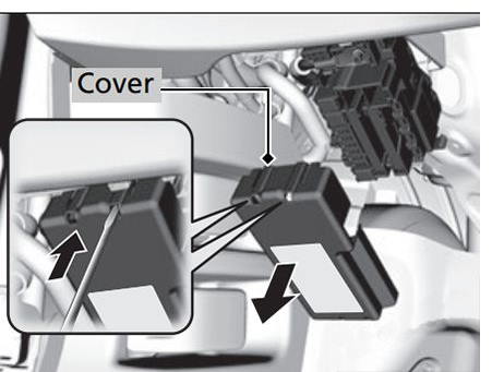
Additional box
This fuse box is under the main one.

Photo

To access, remove the protective cover.
Diagram

Designation
| 1 | 70A EPS |
| 1 | 30A (with smart access system), 50A (without smart access system) – IG Main |
| 1 | 50A Main fuse box 2 |
| 1 | 40A ABS/VSA Motor |
| 1 | 30A Main fuse box 1 |
| 1 | 40A Main fuse box 3 |
| 2 | – |
| 2 | – |
| 2 | – |
| 2 | – |
| 2 | – |
| 2 | – |
| 2 | – |
| 3 | 30A Heater |
| 4 | 30A IG Main 2 (with intelligent entry system) |
| 5 | 30A ABS/ VSA FSR |
| 6 | 10A Deicer |
| 7 | – |
| 8 | – |
| 9 | 10A Small light |
| 10 | 20A ACC connector (console) (optional) |
| 11 | 30A Rear heater |
| 12 | Not used (with smart login system) |
| 7.5A ACC key lock (without smart entry system) | |
| 13 | 10A Heated mirrors (optional) |
| 14 | 7.5A Air conditioning fan SW |
| 15 | Not used (with smart login system) |
| 30A Wiper (without smart entry system) |
Engine compartment
Under the hood, in the engine compartment, on the left side, there are two fuse boxes.
Fuse and relay box

Photo

An example of a circuit from the block cover

Diagram

Allocation
| 1 | 20A Headlight low beam main |
| 2 | 30A CDC (optional) |
| 3 | 10A Alarm / Hazard |
| 4 | 15A DBW |
| 5 | 30A Wiper |
| 6 | 10A Stop |
| 7 | 15A IGP |
| 8 | 15A Ignition coil |
| 9 | 10A ECP (optional) |
| 10 | 20A Injector |
| 11 | – |
| 12 | 30A Main fan |
| 13 | 30A Starter SW |
| 14 | 7.5A MG Clutch |
| 15 | 7.5A Battery sensor |
| 16 | – |
| 17 | 7.5A Daytime running lights |
| 18 | 10A Signal / Horn |
| 19 | 15A Fog lights (optional) |
| 21 | 15A Back Up Main |
| 22 | 7.5A Interior lighting |
| 23 | 30A Sub Fan |
| 24 | – |
| 25 | 7.5A Smart Entry Auto Start (optional) |
| 26 | 7.5A ST MG |
| 27 | – |
| 28 | – |
| 29 | 10A Reversing light |
| 30 | 10A IGPLAF |
| 31 | 7.5A IGPS |
| 32 | 10A Right Headlight Low Beam |
| 33 | 10A Left Headlight Low Beam |
Relays

Power fuse box
The main power block of high power fuses is mounted on the positive terminal of the battery, made in the form of high power fuse links.

Diagram

Appointment
- a – 100A Battery
- b – 70A RB Main 1
- c – 80A RB Main 2
- d – 70A CAP Main
We have also posted a video for this post on our YouTube channel. Watch and subscribe to the channel.
There is something to add – write in the comments.
Fuse for radio Honda grace