The 1st generation Honda CR-V is a compact crossover produced by Honda in 1995, 1996, 1997, 1998, 1999, 2000, 2001 with several body options: Rd1 Rd2 Rd3. During this time, the model has been restyled. In this publication you will find a description of fuses and relays Honda CRV 1 with fuse box diagrams, photo examples of their performance and locations. Select the cigarette lighter fuse.

The purpose of the fuses and relays may differ from those shown. Check the information with your diagrams on the cover of the blocks.
Is it the wrong model generation, or do these fuse box diagrams not apply to your vehicle?
[Description of Honda CRV 6]
[Description of Honda CRV 5]
[Description of Honda CRV 4]
[Description of Honda CRV 3]
[Description of Honda CRV 2]
Passenger compartment
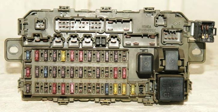
In the cabin, the main fuse and relay box is located at the bottom of the instrument panel on the driver’s side and is covered with a protective cover.
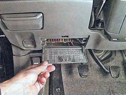
The fuse box itself will look something like this.
Diagram
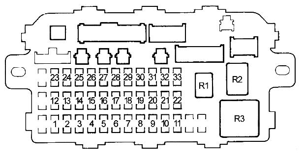
Assignment
| 1 | 15A Heated mirrors, front fog lights |
| 2 | 30A Headlight washer, heated mirrors |
| 3 | 10A Rear wiper, rear wiper control unit (’95-’97) |
| 4 | 10A Right headlight (high beam), daytime running lights |
| 5 | 10A Left headlight (high beam), daytime running light, high beam indicator |
| 6 | 10A Rear outlet |
| 7 | 20A Rear left power window |
| 8 | 20A Rear right power window |
| 9 | 15A Ignition control unit |
| 10 | 20A Front passenger window |
| 11 | 20A Driver’s window regulator, window regulator control unit |
| 12 | 7.5A Hazard and turn signal relay |
| 13 | 15A Main relay of the engine control unit (PGM-FI Main) (fuel pump), airbag control unit (SRS) |
| 14 | 7.5A Cruise control |
| 15 | 7.5A Alternator, charge indicator, electrical load sensor (ELD), EVAP system, oxygen sensors (HO2S), speed sensor (VSS) |
| 16 | 7.5A ABS control unit |
| 17 | 7.5A A/C Compressor Clutch Relay, Heater Relay (High Speed), Heater Relay, A/C Fan Relay, Heater Control Module, Cooling Fan Relay, Recirculation Mode, Power Mirrors |
| 18 | 7.5A Daytime running lights |
| 19 | 7.5A Reversing lamps, reversing lamp relay (A/T) |
| 20 | 7.5A Daytime running lights |
| 21 | 10A Right headlight (low beam) |
| 22 | 10A Left headlight (low beam) |
| 23 | 10A Airbag control unit (SRS) |
| 24 | 7.5A Power window relay |
| 25 | 7.5A Instrument Cluster, Integrated Control Unit, ABS Indicator, Gear Indicator, Clock (’98-’01), Cruise Control Indicator, Transmission Selector (A/T) Lockout, Central Locking Control Module , airbag indicator |
| 26 | 20A Wiper and washer, integrated control unit |
| 27 | 10A Front outlet (cigarette lighter), rear outlet |
| 28 | 10A Audio system |
| 29 | 7.5A Rear fog lamp |
| 30 | 7.5A Instrument cluster, body electronics (Integrated Control Unit), gear indicator, audio system, clock, cruise control indicator, instrument panel illumination, instrument cluster illumination, alarm indicator, heater control unit, power window control unit (’99 -’01) |
| 31 | 7.5A Engine Control Module (ECM (’98-’01: M/T)), Powertrain Control Module (PCM (A/T)), Engine Control Module Main Relay (PGM-FI Main), Body Electronics Module ( integrated control unit) |
| 32 | 7.5A Clearance light, license plate light, trailer connector |
| 33 | 7.5A Ignition switch illumination, gear selector lock, key lock |
| Relay | |
| R1 | Rear window heating |
| R2 | Power windows |
| R3 | Hazard and direction indicators |
The rest of the fuses are spare.
Fuses number 6 and 27 are responsible for the operation of the cigarette lighters.
Engine compartment
Under the hood, in the engine compartment of the Honda CR-V 1, there are two boxes: the main fuse and relay box (1) and the ABS fuse box (2).

Fuse and relay box
Photo – example

Scheme from the block cover

Diagram

Designation
| 1 | 100A Battery (BATTERY); |
| 2 | 15A Horn and brake signals (HORN STOP); |
| 3 | 10A Hazard signaling (HAZARD); |
| 4 | 30A Headlights (HEAD LIGHT); |
| 5 | Reserve |
| 6 | 40A Starter relay and ignition switch circuit (IG1); |
| 7 | 40A Power windows (POWER WINDOW); |
| 8 | 7.5A Interior lighting (INTERIOR LIGHT); |
| 9 | 15A ECU engine management system (FI E / M); |
| 10 | 7.5A Reversing lamp (BACK UP); |
| 11 | 20A Rear window heating element (RR DEFROSTER); |
| 12 | 20A Central locking and electric ventilation hatch (DR LOCK UNIT. ROOF); |
| 13 | 10A Air conditioner radiator electric fan; |
| 14 | 40A Electric heater fan; |
| 15 | 20A Electric fan of the engine cooling system (COOLING FAN); |
| 16 | Switch on relay (HEATER MOTOR RELAY); |
| 17 | 40A Heater motor (HEATER MOTOR); |
| 18 | Relay for turning on the electric fan of the engine cooling system (COOLING FAN RELAY); |
| 19 | Relay for switching on the air conditioning system (MG. CLUTCH RELAY); |
| 20 | Relay for turning on the electric fan of the radiator of the air conditioner (CONDENSER FAN RELAY) |
ABS fuse box
Diagram

Allocation
- ABS pump activation relay (PUMP MOTOR RELAY);
- 7.5A ABS electric pump (MTR CHECK);
- 20A ABS electrical equipment (ABS+B);
- 40A ABS electric pump motor (PUMP MOTOR)
There is something to add – write in the comments.
Where is the headlight relay(s) located in a 2001 Honda CRV?