Honda City 5th generation was produced in 2008, 2009, 2010, 2011, 2012, 2013, and 2014 with the model designations GM2 and GM3. Also known as Honda Ballade. Produced in Pakistan until 2021. During this time, the model received an update. In this post, we will provide a description of the Honda City 5 Ballade fuses and relays, including fuse box diagrams, their locations, and photo examples. Also we will highlight the fuse responsible for the cigarette lighter.

The purpose of the fuses and relays and their location may differ from those shown and depend on the year of manufacture, the level of electrical equipment and the region where your car was delivered.
Is it the wrong model generation, or do these fuse box diagrams not apply to your vehicle?
[Description of Honda City 6]
[Description of Honda City 7]
Passenger compartment
The main fuse and relay box is located in the passenger compartment, under the instrument panel on the driver’s side.
Location

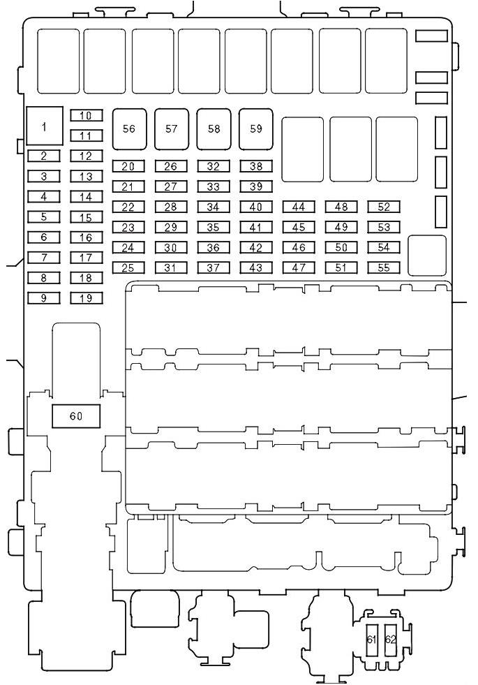
To access, remove the protective cover. The block itself will look something like this.

Check the information with your diagrams.
An example of a diagram with a designation
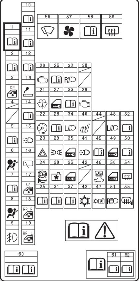
Diagram
Assignment
| 1 | 10A Reversing lights |
| 2 | 7.5A Tire pressure monitoring system |
| 3 | 20A Power window regulator on the driver’s side |
| 4 | Reserve |
| 5 | 10A Reversing lights |
| 6 | 10A Supplemental Restraint System (SRS) |
| 7 | 10A Gearbox control unit |
| 8 | 7.5A Passive Safety System (SRS) |
| 9 | 20A Fog lights |
| 10 | 7.5A Air conditioner |
| 11 | 7.5A Anti-lock braking system AC (ABS) |
| 12 | 10A Generator |
| 13 | 20 Cigarette lighter, Socket for connecting additional equipment |
| 14 | 7.5A Auxiliary equipment |
| 15 | 7.5A Daytime lighting system |
| 16 | 10A Windshield wiper and rear door glass washer |
| 17 | 20A Power window regulator on the front passenger side |
| 18 | 20A Electric power window rear right door |
| 19 | 20A Power window lifter rear left door |
| 20 | 15A Gasoline pump |
| 21 | 15A Windshield washer |
| 22 | 7.5A Instrument cluster |
| 23 | 10A Alarm |
| 24 | 15A Stop lights, horn |
| 25 | 15A Windshield wiper drive |
| 26 | 10A Heater |
| 27 | 30A Central lock |
| 28 | 20A Lights |
| 29 | 10A Side lights |
| 30 | 30A Cooling fan motor |
| 31 | Reserve |
| 32 | 10/15A Right headlight (dipped beam) |
| 33 | 15A Ignition |
| 34 | 10A Left headlight (high beam) |
| 10A Left headlight (dipped beam) | |
| 35 | 15A Electric door lock |
| 37 | 30A Anti-lock braking system ABS (ABS), Vehicle Stability Control (VSA) |
| 38 | 15A Electric door lock |
| 39 | 15A Engine management system |
| 40 | 20A Heated front seats |
| 41 | Daytime Running Lights |
| 42 | Reserve |
| 43 | 7.5A Air conditioning compressor electromagnetic clutch |
| 44 | 7.5A STS |
| 45 | 20A Electric door lock |
| 46 | 20A Roof blind motor |
| 47 | 30A Cooling fan motor |
| 48 | 10/15A Left headlight (dipped beam), left headlight (high beam) |
| 49 | 15A Gearmotor 2 (Unlock) door lock |
| 50 | 15A Gearmotor 1 (Unlock) door lock |
| 51 | 10A Right headlight (high beam) |
| 52 | 15A DBW |
| 53 | Reserve |
| 54 | 20A Heated rear window |
| 55 | 10A Heated side mirrors |
| 56 | 30A Windshield wipers |
| 57 | 30A Heater fan motor |
| 58 | 30A Anti-lock braking system (ABS), Vehicle Stability Control (VSA) |
| 59 | 20/30A Heated rear window |
| 60 | 40/50A Ignition |
| 61 | 30A Audio system |
| 62 | Reserve |
| R1 | Power window relay |
| R2 | Heater fan motor relay |
| R3 | Ratio Sensor Relay |
| R4 | Lighting Relay #1 |
| R5 | Ignition coil relay |
| R6 | Engine Management Relay #1 |
| R7 | Relay (Drive By Wire) Control System |
| R8 | Rear defroster relay |
| R9 | Lighting Relay #2 |
| R10 | Starter relay |
| R11 | Engine Management System Relay #2 (FUEL PUMP) |
The number 13 fuse is responsible for the cigarette lighter.
Relays diagram

Description
- 1 – Power Window Relay
- 2 – Blower Motor Relay
- 3 – A/F Sensor Relay
- 4 – Headlight Low Beam Relay
- 5 – Ignition Coil Relay
- 6 – PGM-FI Main Relay 1
- 7 – ETCS Control Relay
- 8 – Rear Window Defogger Relay
- 9 – Starter Cut Relay
- 10 – PGM-FI Main Relay 2
- 20 – Driver’s Door Unlock Relay
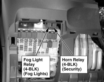
In the upper part, some additional relays can also be attached.
Engine compartment
Power fuse box
A power side made in the form of high-power fusible links is attached to the positive terminal of the battery.
Diagram
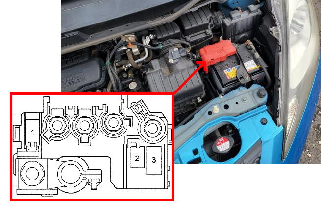
Appointment
- 100A – Battery
- 60/70A – Electric power steering
- 20A – Horn, brake lights, hazard warning
Additional elements
Layout

Allocation
- Pressure modulator and VSA control unit or pressure modulator and ABS control unit
- Electronic engine control unit
- Additional relay box №2
- Compressor magnetic clutch relay
- Cooling Fan Motor Relay
- Brush defroster relay
- Additional relay box №1
- Condenser fan motor relay.
We have also posted a video for this post on our YouTube channel. Watch and subscribe to the channel.
Found a mistake or have something to add – write in the comments.