Daewoo Nexia (Cielo) has been produced since 1994 with sedan and hatchback bodies. Daewoo Nexia n100 was assembled in 1995, 1996, 1997, 1998, 1999, 2000, 2001, 2002, 2003, 2004, 2005, 2006 and 2007. After that, the model underwent restyling and the updated Nexia n150 was delivered to the markets in 2008, 2009, 2010, 2011, 2012, 2013, 2014 and 2015. Also known as Chevrolet Nexia. In this article you will find a designation of the Daewoo Nexia fuse and relay boxes with diagrams and photographs. Let’s highlight the fuse responsible for the cigarette lighter.
The main fuse and relay box is located in the passenger compartment under the dashboard on the driver’s side behind the protective cover.
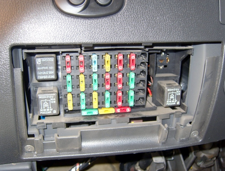
On the back of the cover you can find the current diagram of your Daewoo Nexia.

Contents
Fuse box
The main fuse and relay box consists of two sections: the main relay fuse section and an additional section.
Main department of fuses and relays
Diagram

Protected components
F1 (10 A) – electronic engine control unit (ECU) .
F2 (10 A) – side lights .
If the dimensions do not work for you, check the light and turn signal switch knob, it could fail or the contacts / wires at its base could be damaged. Also check the contacts of this fuse, it happens that they burn, clean them and achieve good contact of the fuse in the socket. The reason may also be in the relay and its contacts. It is also possible that the tracks in the mounting block have burned out.
If the fuse blows very often, then there is a short circuit somewhere. Check the connectors in each headlight, as well as the wires, especially those that go in harnesses along the bottom of the car. They could be transmitted or cut off. A general wiring diagram and connectors at the end of this article. Do not forget to check the side light bulbs themselves, it happens that they all burn out at the same time or one after the other.
F3 is reserved .
F4 (20 A) – high beam headlights .
To turn on the high beam, you need to move the left handle under the steering wheel to a position farther from you. To blink, pull on yourself.
If your high beam does not work, check the health of the lamps (both could burn out at once), the health of the relays and their contacts, the contacts in the fuse socket. The steering column switch can also be one of the reasons. If the above is correct, most likely the matter is in the wiring or contacts in the headlight connectors.
F5 (10 A) – low beam, left headlight electrocorrector .
F6 (10 A) – low beam, right headlight electrocorrector .
If the high beam works, but the low beam does not, most likely the matter is in the steering column light switch, check its contacts and wires, the strength of the connectors. You can remove the switch, carefully disassemble it and check the plates for a short circuit, as well as the plastic switch, whether it reliably opens the contacts. Do not forget to check the health of the lamps in the headlights, even if both dipped headlights do not work, as well as the contacts in the connectors and wires. The reason for the lack of light may be in the contact group of the ignition switch. If you are not versed in electrics, it is better to contact the service.
F7 (30 A) – fuel pump, fuel injectors .
If the fuel pump stops working, check the contacts in the fuse socket, as well as the relay and its contacts. If they are oxidized or there are traces of burning, replace the relay. There may be no contact in the ignition switch or contact group. If there are interruptions in the operation of the fuel pump, the engine starts, then no, most likely a relay, or perhaps the matter is in the fuel filter that needs to be replaced.
At low temperatures and their differences, a condensate evaporator can help, which is poured into the tank along with gasoline. Also, due to low-quality gasoline, the pump itself may fail. You can check it by applying a voltage of 12 V to it directly, or by connecting a hose lowered into the container instead of the fuel line.
The fuel pump may also not work due to the wiring in the cabin at the bottom left of the driver, near the left front fender. To get to the wires, you need to remove the trim to the left of the clutch pedal. When you see the connector block, check all the wires and connections coming from it. The yellow-brown or white-brown wire is responsible for the operation of the gas pump. Also check that the wires are not interrupted by possible self-tapping screws screwed into the body.
If nothing described helps and an unloading relay is installed in the contact group of the ignition switch, check it and replace it if necessary.
F8 (20 A) – turn signals, alarm, brake lights .
If the direction indicators stop working, first of all check this fuse and relay-breaker, as well as its contacts. If the turn signals work intermittently, the point is most likely in the same relay, in the wiring or in a short circuit in the turn signal connectors. If, when the direction indicators are turned on, neither the turn signals nor the warning lamps on the dashboard work, most likely the matter is in the steering column switch, its contacts or relay.
If the “emergency gang” does not work, most likely the matter is also in the relay, in the button itself and its contacts, or in the wiring from the button to the fuse / relay.
Do not forget to also check the turn signal bulbs themselves.
F9 (30 A) – wiper, washer .
If the “wipers” do not work, look at the relay and its contacts. Check whether the gear motor itself is working by applying a voltage of 12 V to it, whether the nuts on the shafts of the wiper holders are tightly tightened, whether the trapezium mechanism is working properly. Check the serviceability of the right steering column switch, contacts and wires in its connector. Another reason for the incorrect operation of the cleaner motor may be poor ground contact. Try to directly connect a wire between the car body and the motor body and check its operation.
If the outside temperature is low, check if the wiper mechanism is frozen, especially the shafts with nuts, if necessary, clean it of ice and moisture.
F10 (10 A) – electric drive for the lock of the gas tank lid .
F11 (10 A) – air conditioning compressor relay .
In order for the air conditioner to work properly after winter, it is recommended to turn it on from time to time in a warm place (garage, box, car wash) in winter so that the sealing joints are lubricated. Otherwise, they will have to be changed in the spring. At low temperatures, due to lack of pressure, the air conditioner will not turn on.
If the air conditioner stops working, check, in addition to this fuse, also the relay. Perhaps the system has run out of freon. You can check by unscrewing the cap on the side of the receiver, located near the battery. By pressing the valve, the freon should hiss out of the hole, which means there is pressure and gas.
If there is no pressure, check the pressure sensor installed on the tube near the air filter. When the contacts in the two-pin connector of the pressure sensor are closed, the air conditioner must turn on. Fill the system with freon, after checking the system for leaks. There may be leaks in connections, pipes and the radiator of the air conditioner.
The matter may also be in the clutch, which, when the air conditioner is turned on, should move (a click will be heard), if it does not work, check its connector, you can also check by applying a voltage of 12 V to it, access to the contacts is only from below, it is most convenient to get from the examination room pits. The compressor may also be faulty or its belt may break, check for the presence of a whole and tensioned lower belt in the front of the engine (under the upper belt of the generator).
If the air from the air conditioning system enters the passenger compartment poorly or not cold enough, check the cabin filter and replace it. The evaporator may also be clogged, check and clean it.
F12 (30 A) – low speed of the radiator cooling fan .
If the fan only runs at high speed, check this fuse, the contacts in its socket, and relays B and K.
F13 (20 A) – dashboard, clock, cigarette lighter, buzzer, reversing lamps, generator, heated rear window .
F14 (30 A) – sound signal, high speed of the radiator cooling fan .
If the horn does not work, check the fuse and contacts in its socket, as well as the relay. If the signal frequency has changed or the signal has disappeared altogether, most likely the matter is in the wiring to one of the horns. 2 signals – 2 tones. Check the contacts and wires at the horns by removing the radiator grill, they usually rot due to moisture. Also check the steering column contact of the horn button and its mechanism.
If the radiator fan stops turning on at high temperatures, check the health of the relay and their contacts. Check the fan sensor, disconnect the contacts from it and close them, the fan should turn on. Or apply a voltage of 12 V directly to the fan connector, thereby checking the serviceability of its electric motor, check this connector for connecting wires to the fan for oxidation of the contacts.
If the fan motor is running, it could be a fuse and relay, wiring, thermostat, and coolant temperature sensor. If you check the wiring, from the temperature sensor to the ECU, from the ECU to the relay.
F15 (20 A) – interior light, trunk light, aerial drive .
If the light in the plafond near the rearview mirror does not work only in the “Auto” position, check the limit switches in the doors and wiring, as well as the light mode switch itself. The wiring from the limit switches is harnessed in the driver’s door sill or under the driver’s seat, check the integrity of all wires.
If the light does not work in any of the modes, check the serviceability of the lamp and the switch in the shade.
If the light in the trunk does not work, check the lamp on the left side of the trunk, the lamp contacts and the wiring.
F16 (30 A) – power windows .
If your windows stopped working, most likely the matter is in the wiring. Check the wires going to the doors to see if they are broken at the folds (in the corrugated elastic bands), a standard disease of many Nexia models. Also check the performance of the motors by applying a voltage of 12 V to them and the condition of the brushes in them. If one window regulator does not work, the matter may also be in the door wiring or in the window regulator control button, check its contacts and serviceability.
Also check the mechanism itself in the door for defects and jamming, the condition of the gear and cable. The reason may be in the driver’s power window control unit. Check it for a short circuit.
If the glass begins to warp, due to which the window regulator cannot cope with it, try to completely lower the glass and lubricate the sealing rubber strips with WD-40 liquid or silicone.
F17 (10 A) – power supply of the radio from the ignition lock .
Usually the radio is connected in such a way that it works only when the ignition is on. If you want the radio tape recorder to work constantly, find the place of its connection in the contact group of the ignition switch and connect it to a constant 12 V power supply through a fuse. If the radio tape recorder stops working, check the ignition switch, the contacts in it, the contact group and the wiring.
F18 (30 A) – power supply of the radio from the battery, heated rear window, electric trunk lock, central locking .
Heated rear window in Nexia is automatically switched off. If it does not work for you, check this fuse, F13 and the contacts in their sockets, as well as the relay and its contacts. The heating timer relay can be installed not in the mounting block, but under the dashboard, just above the pedal unit. Also check the button itself and its contacts. The reason may be in the wiring from the button to the rear window, it could be transmitted to the bottom of the car. Check the terminals of the heating elements of the rear pillars along the edges of the glass and the absence of broken threads on the glass. If you find a break, glue it with a special glue containing metal.
If the central locking does not work and some door does not close, remove the casing from it and check the correct operation of the lock drive and the serviceability of the traction. If the lock is 5-pin, check the health of all its contacts and wiring. Also check the wires in the corrugation at the fold when opening the door. The case may also be in the central locking relay, which is located behind the electronic control unit (ECU), on the passenger side of the center console.
The fuse number 13, 20A, is responsible for the cigarette lighter.
Relay assignment
| K1 | Cooling fan (high speed) |
| K2 | Direction indicators. |
| K3 | Fuel pump. |
| K4 | Fog lights. Rear fog lights. |
Additional compartment for fuses and relays
F20 (30 A) – air conditioner fan .
F21 (30 A) – fog lights .
If the “fog lights” stopped burning, check the fuse, the contacts of its socket, the serviceability of the lamps in the headlights, the power button in the passenger compartment, the wiring, the relay and its contacts.
Nexia n100
Diagram

Designation
| 5 | Air conditioner fan (maximum speed) |
| 6 | Intermittent wiper mode |
| 7 | Heated rear window (with automatic shutdown function) |
| 8 | Low beam headlights (when the high beam lamps are turned on) |
| 9 | Sound signal |
| 10 | Air conditioning compressor |
| 11 | Cooling fan (low speed) |
| 12 | Headlights |
| 13 | Outdoor Lighting |
| fourteen | Buzzer |
Nexia n150
Diagram

Assignment
| 5 | Air conditioner fan (maximum speed) |
| 6 | Intermittent wiper mode |
| 7 | Heated rear window (with automatic shutdown function) |
| 8 | Low beam headlights (when the high beam lamps are turned on) |
| 9 | Sound signal |
| 10 | Air conditioning compressor |
| 11 | Cooling fan (low speed) |
| 12 | Headlights |
| 13 | Outdoor Lighting |
| 14 | Buzzer |
On our YouTube channel, we also posted a video. Watch and subscribe.
Still have questions? Ask them in the comments.