The Tank 500 was produced in 2021, 2022, 2023, 2024, 2025, 2026, 2027, 2028, and 2029. During this time, the model received an update. In this publication, you can find a description of the Tank 500 fuses and relays, along with block diagrams and their locations. Note the cigarette lighter fuse.

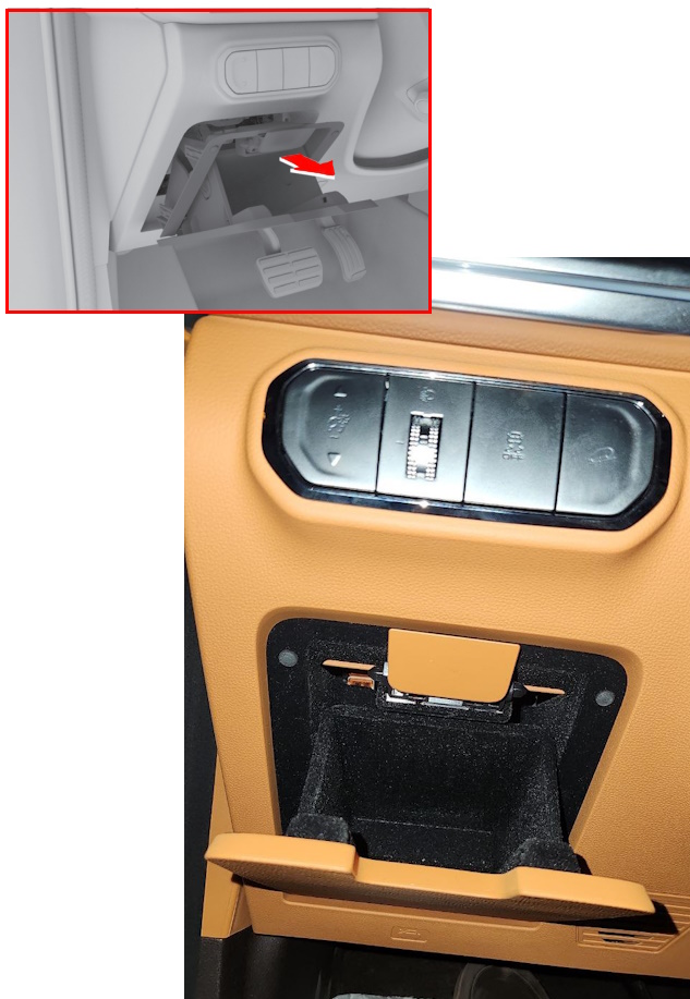
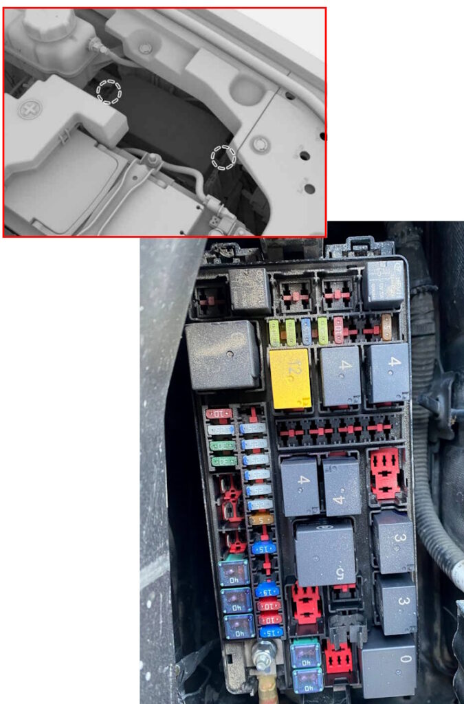
Passenger compartment
It is located behind the glove compartment on the driver’s side. To access, pull firmly on the right side in the direction of the arrow.
The block itself will look something like this.
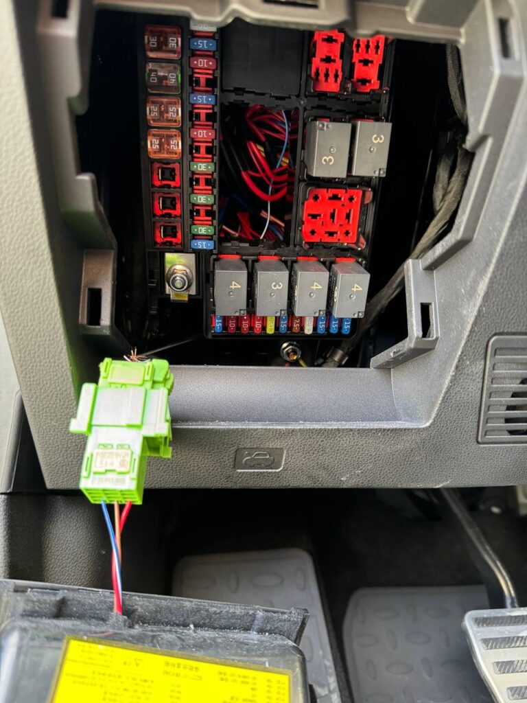
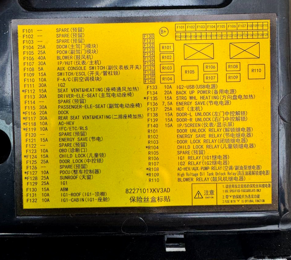
Check the assignment against your diagrams on the back of the protective cover.
Diagram
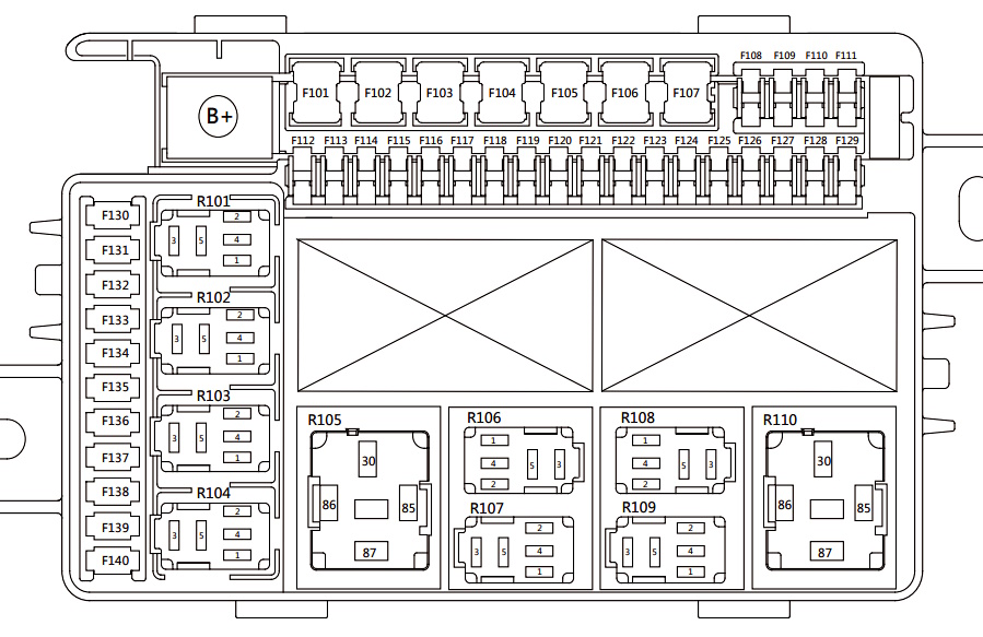
Assignment
| F101 | Reserve |
| F102 | Reserve |
| F103 | Reserve |
| F104 | Driver Door Module — 25A |
| F105 | Front Passenger Door Module — 25A |
| F106 | Blower (Heater/Air Conditioner Fan) — 40A |
| F107 | Instrument Cluster/Head Unit (Multimedia) — 30A |
| F108 | Electronic Shift Selector (Shift-by-Wire) — 5A |
| F109 | Switch Module (Control Button Module) — 15A |
| F110 | Front Climate Control Module — 10A |
| F111 | IG2 (Ignition 2 Circuit) — 30A |
| F112 | Front Passenger Seat Heater/Blower* — 15A |
| F113 | Driver Power Seat — 30A |
| F114 | Driver Power Seat Heater/Blower* — 15A |
| F115 | Front Passenger Power Seat — 30A |
| F116 | DOCK Power Supply (Accessory Docking Station/Port)* — 20A |
| F117 | Second Row Seat Heaters* — 30A |
| F118 | AC-HEV (hybrid air conditioning system)* — 10A |
| F119 | IFC / ETC / RLS* (camera, electronic control, rain/light sensor) — 10A |
| F120 | Spare |
| F121 | Node relay input (powered via main relay) — 15A |
| F122 | Spare |
| F123 | OBD-II diagnostic connector — 10A |
| F124 | Child locks* — 15A |
| F125 | Central door locking — 25A |
| F126 | Spare |
| F127 | Vehicle control unit* — 10A |
| F128 | Sunroof — 25A |
| F129 | IG1 (main ignition circuit #1) — 25A |
| F130 | ABM (Airbag Module) — 15A |
| F131 | IG1-ceiling (ignition circuits for ceiling units) — 10A |
| F132 | IG1-cabin (ignition circuits for cabin units) — 10A |
| F133 | USB / wireless charging — 10A |
| F134 | Backup Power Supply — 20A |
| F135 | Heated Steering Wheel — 15A |
| F136 | IG1 (Ignition 1 Circuit) — 10A |
| F137 | HUT (Head Unit, Multimedia System) — 25A |
| F138 | Left Door Unlock via Central Locking — 15A |
| F139 | Right Door Unlock via Central Locking — 15A |
| F140 | Instrument Panel Indicator/Display — 15A |
| R101 | Central Locking Release Relay |
| R102 | Power Saving Relay |
| R103 | Central Locking Relay |
| R104 | Child Lock Relay |
| R105 | Backup |
| R106 | IG1 Relay (Ignition 1 Circuit) |
| R107 | IG2 Relay (Ignition 2 Circuit) |
| R108 | Air Conditioner Relay |
| R109 | Power Steering Column Relay |
| R110 | Heater Blower Relay |
Engine compartment
In the engine compartment, the fuse box is located on the right side, next to the battery.
Diagram

Designation
| F201 | ESP1 (Electronic Stability Program) – 40A |
| F202 | ESP2 – 40A |
| F203 | Main Relay – 40A |
| F204 | Spare |
| F205 | Spare |
| F206 | * Condenser Fan (Air Conditioner) – 30A |
| F207 | Windshield Wiper Motor – 30A |
| F208 | Starter – 30A |
| F209 | TCU (Transmission Control Unit) – 25A |
| F210 | Headlight High/Low Beam Adjustment – 10A |
| F211 | ECU (Engine) – 15A |
| F212 | BSG/DCDC (Integrated Starter-Generator + Voltage Converter, 48V) – 10A |
| F213 | Compressor (Air Conditioner) – 10A |
| F214 | Washer Motor – 15A |
| F215 | * Heated Windshield Wipers – 10A |
| F216 | Spare |
| F217 | Horn – 15A |
| F218 | Spare |
| F219 | Brake Light Switch – 5A |
| F220 | CEM1 (Central Electronic Module (Central Electronic Module, Power Supply) – 25A |
| F221 | CEM2 (Central Electronic Module, Power Supply) – 25A |
| F222 | CEM3 (Central Electronic Module, Power Supply) – 25A |
| F223 | CEM4 (Central Electronic Module, Power Supply) – 25A |
| F224 | CEM5 (Central Electronic Module, Power Supply) – 25A |
| F225 | CEM6 (Central Electronic Module, Power Supply) – 25A |
| F226 | Reserve |
| F227 | Reserve |
| F228 | Reserve |
| F229 | Reserve |
| F230 | Reserve |
| F231 | Reserve |
| F232 | Reserve |
| F233 | Reserve |
| F234 | Reserve |
| F235 | Reserve |
| F236 | Reserve |
| F237 | IRC3 (Integrated Relay Controller, Circuit 3) – 20A |
| F238 | IRC1 (Integrated Relay Controller, Circuit 1) – 20A |
| F239 | IRC2 (Integrated Relay Controller, Circuit 2) – 15A |
| F240 | IRC4 (Integrated Relay Controller, Circuit 4) – 20A |
| F241 | IG1 (Ignition, Power Circuit After Ignition, IGNITION Position 1) – 10A |
| F242 | Reserve |
| F243 | Reserve |
| F244 | Engine Start Feedback Signal – 5A |
| R201 | Compressor Relay (Air Conditioner) |
| R202 | Windshield Wiper Defogger Relay |
| R203 | High Beam Relay |
| R204 | Horn Relay |
| R205 | Reserve |
| R206 | Main Relay |
| R207 | Windshield Wiper Power |
| R208 | Windshield Wiper Speed |
| R209 | Reserve |
| R210 | Reserve |
| R211 | Starter Relay 1 |
| R212 | Starter Relay 2 |
| R213 | Reserve |
| R214 | Reserve |
| R215 | Condenser Fan High Speed |
| R216 | Condenser Fan High/Low Speed |
| R217 | Windshield Washer |
| R218 | Rear Window Washer |
| R219 | Reserve |
A high-power fuse block in the form of fusible links is installed on the positive terminal of the battery.
Diagram
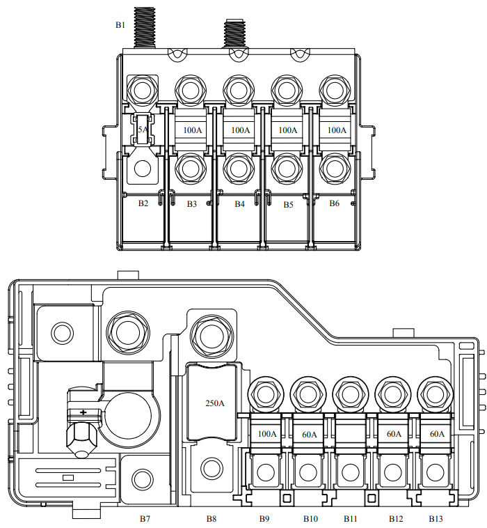
Allocation
- B1 – Starter
- B2 – EBS 5A
- B3 – EPS 100A
- B4 – Dashboard Fuse Box 100A
- B5 – Trunk Fuse Box 100A
- B6 – Engine Compartment Fuse Box 100A
- B7 – Reserve
- B8 – DC-DC Converter 250A
- B9 – Fan 100A
- B10 – iBooster 60A
- B11 – Reserve
- B12 – Inverter, 220V 60A
- B13 – TCU 60A
Luggage compartment
In the luggage compartment, the fuse and relay box is located inside the left or right wall of the luggage compartment.
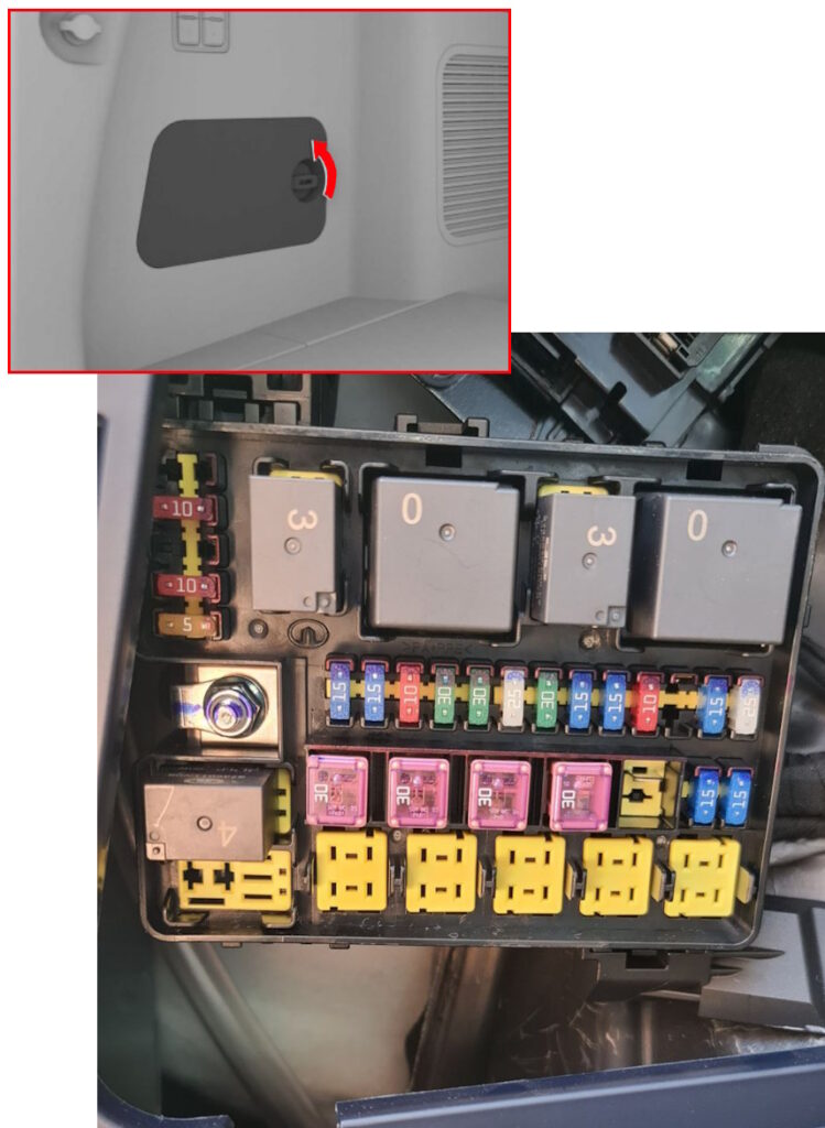
Block cover diagram

Diagram
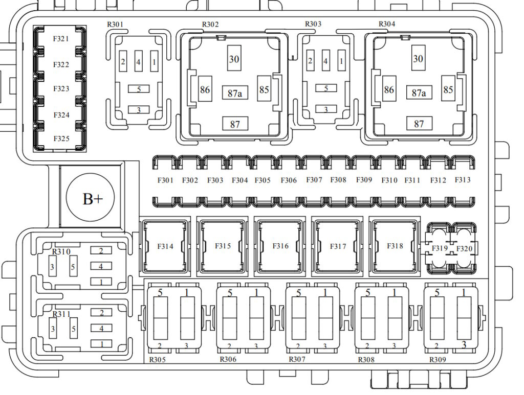
Description
| F310 | Rear Window Wiper – 10A |
| F311 | Spare |
| F312 | Tailgate Lock/Closer/Electronic Damper – 15A |
| F313 | Rear Window Defogger – 25A |
| F314 | Door Closer Controller/Third Row Seat Folding Motor – 30A |
| F315 | Blower (Heater Fan) – 30A |
| F316 | Pedal Controller (Electronic Accelerator Pedal) – 30A |
| F317 | Audio Amplifier/T-BOX Module (Telematic Communication Unit) – 30A |
| F318 | Spare |
| F319 | Power Amplifier 1 – 15A |
| F320 | Power Amplifier 2 – 15A |
| F321 | Spare |
| F322 | IG1 (Ignition Circuit, Power After Ignition Switch) – 10A |
| F323 | Spare |
| F324 | Exterior Rearview Mirror (Heated/Powered) – 10A |
| F325 | T-BOX (Telematics Unit) – 5A |
| R301 | Trailer Power Socket Relay |
| R302 | Rearview Defogger Relay Glass |
| R303 | Fuel pump relay |
| R304 | Rear air blower relay (rear heater fan) |
| R305 | Reserve |
| R306 | Reserve |
| R307 | Reserve |
| R308 | Reserve |
| R309 | Auxiliary fuel pump relay |
| R310 | Rear wiper relay |
| R311 | * Tailgate lock relay |
We have a video on this topic on our channel, watch and subscribe.
If you know how to make the post better, write in the comments.