Volvo FH 12 represents the 1st generation of the heavy duty truck family which was produced in 1994, 1995, 1996, 1997, 1998, 1999, 2000, 2001, 2002, 2003 and 2004. During this time, the model has been restyled. In our material you will find a description of the fuses and relays Volvo FH 12 with fuse box diagrams, photographs and their locations. Select the fuse responsible for the cigarette lighter. This material will also be useful to owners of Volvo FH 16.

The purpose of the fuses and relays may differ from the one shown and depends on the year of manufacture, modification and level of electrical equipment of your car. Check the information with your diagrams on the block cover.
Diagram is wrong? Chek the description for Volvo FH 13.
Contents
Passenger compartment
Layout

Block D
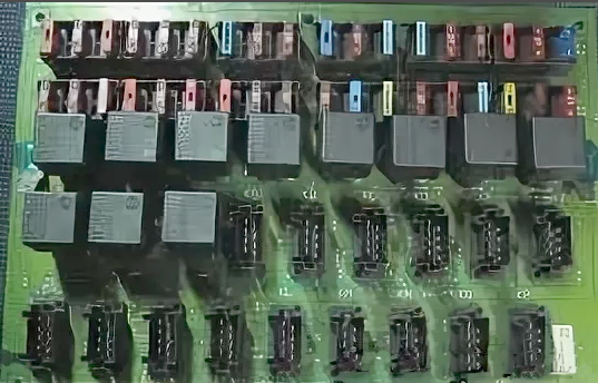
To access, remove the protective cover.

The fuse box itself will look something like this.
Type 1
Diagram

Assignment
Fuses
- F1 – low beam headlights left
- F2 – dipped beam headlights right
- F3 – auxiliary heater, webasto, radio
- F4 – brake, brake lights, brake light fuse
- F5 – reversing lights, alternator charging lamp, alternator excitation, reverse fuse
- F6 – interior lighting, radio, central locking fuse, interior lighting and sockets
- F7 – alarm
- F8 – turns, warning lights
- F9 – tachograph, clock, emergency gang (alarm), lighting, instrument fuse and tachograph
- F10 – air conditioning, internal heating fan motor
- F11 – automatic transmission, transmission transmission control unit fuse
- F12 – wiper motor and windshield washer, wiper and washer
- F13 – Headlight washers, headlight wiper fuse
- F14 – Searchlight, additional lights, searchlight fuse
- F15 – engine preheating – glow plugs, glow plug fuse
- F16 – cigarette lighter, converter
- F17 – front fog lights, rear fog lights fuse
- F18 – EDC engine control unit
- F19 – high beam, left side, fuse on the wiring diagram for the left headlight
- F20 – high beam right side, fuse on the wiring diagram for the right headlight
- F21 – 24 volt sockets, bedside lamp, interior light fuse
- F22 – reserve
- F23 – air suspension, frame lift
- F24 – dimensions left side
- F25 – searchlight
- F26 – trailer parking light left side, fuse on parking lights wiring diagram
- F27 – air conditioner
- F28 – dimensions right side
- F29 – EDC engine control unit
- F30 – trailer parking light right side
- F31 – differential lock, power take-off
- F32 – sound signal, additional equipment
- F33 – power window on the driver’s side
- F34 – central locking, power window with passage. sides
- F35 – low beam
- F36 – heated mirror
Relay
- 302 – Lighting relay (additional spotlight)
- 305 – Relay for reversing lights
- 306 – Relay low beam headlights
- 307 – Relay high beam headlights
- 308 – Brake light relay brake lights
- 309 – Relay dimensions
- 315 – Starter relay
- 343 – Rear fog lamp relay
- 375 – Daytime Running Light Relay, Alternator
Type 2
Diagram

Designation
Fuses
- F1 Air suspension, hydraulic trolley lift
- F2 Area inhibitors, compressor control
- F3 Airbag, immobilizer
- F4 Central locking
- F5 Interior lighting, timer
- F6 Trailer stops
- F7 Instruments
- F8 Voltage divider for radio
- F9 Stop
- F10 Searchlight
- F11 High beam blink
- F12 Air suspension
- F13 Heated rear-view mirrors
- F14 Heating relay “radiopos”
- F15 Low LHS light
- F16 High LHS light
- F17 Radiopos
- F18 Cooling fan control, heating relay
- F19 Vehicle ECU
- F20 Solenoid valves engine
- F21 Instruments, el. heated mirror relay
- F22 Daylight
- F23 Dryer heating
- F24 Additional equipment
- F25 El. rear view mirrors
- F26 Differential lock, power take-off
- F27 Electronic climate control
- F28 Direction indicator, instruments
- F29 Horn
- F30 Cigarette lighter
- F31 Voltage divider 12V
- F32 Rear fog lights
- F33 Parking light, left
- F44 Clearance light trailer left
- F55 Luggage compartment lighting
- F56 Clearance light right trailer
- F57 Parking light, right
- F58 Direction indicator, danger warning
- F59 Middle right
- F30 Main beam right
- F31 El. power window, passenger side
- F32 El. power window, driver’s side
- F33 Engine ECU
- F34 Reverse light, reverse warning, alarm
- F35 Fan, climate unit
- F36 El heated seat, park. heater
- F37 Wiper
- F38 Windshield wiper headlight and headlight washer
Relay
- 301 Relay, fog lights “9” (CG5)
- 305 Relay, reversing lights “12” (EA7)
- 306 Relay, full beams “11” (CE55)
- 307 Relay, low beam “3” (CE48)
- 308 Relay, brake lights truck “8” (CK8)
- 308V Relay, brake lights trailer “10” (CK15)
- 309L Relay, parking lights left “1” (CE19)
- 309R Relay, parking lights right “2” (CE26)
- 315R Relay starting switch “4” (AA42)
- 343 relay, rear fog lights “7” (CG12)
- 348A Relay, fan, climate unit “13” (HA 6)
- 360 Relay, power take-off inhibitor “14” (LD3) (LE4)
- 379 Relay, fuel injection “5” (AC17)
- 3005 Generator controlled relay “6” (AA52)
- 3101 Relay, interior lamps “15” (ER13) (ES13)
Block E
Connectors
- Х1 – Free
- X2 – Automatic transmission “AG2”
- X3 – Automatic transmission “AGS1”
- X4 – Pneumatic suspension “BL”
- X5 – Anti-lock system “AS”
Fuses
- P1 – Additional heater (20A)
- P2 – Additional heater (15A)
- P3 – Free
- P4 – Free
- P5 – Electric seat heating (15A)
- P6 – Electrical input 12V (15A)
Fuses
- P1 – Solenoid valve, anti-blocking system
- P2 – Solenoid valve, anti-blocking system
- P3 – Relay, control unit (5A)
- P4 – Information block (5A)
- P5 – Diagnostic input (5A)
- P6 – Trailer power (25A)
- K1 – Searchlights “302”
- K2 – Air suspension, level adjustment “3014A”
- K3 – Air suspension, level adjustment “3014B”
- K4 – Pneumatic suspension “3014C”
- K5 – Seat adjustment “3076”
- K6 – Rear-view mirrors with electric heating
- K7 – Air suspension, bogie lift “314D”
- K8 – Air suspension, strut lift “314E”
- K9 – Automatic transmission, EEC. engine braking ADR “345V” “318A” “309AB”
- K10 – Automatic transmission, EEC, engine braking ADR “3073” “318V” “309AL”
Anti-lock fuses
- K1 – Solenoid valve, anti-lock braking system
- K2 – Stop lights, trailer
- K3 – Solenoid valve, anti-lock braking system
- K4 – Indicators, anti-lock braking system
Block H
Block of additional equipment (optional). Located at the bottom right of the diagram. There may be protection elements here: Air conditioner, Control unit, Parking heater (water), etc.
Block G
Electronic blocks
- Multifunction relay
- EDC system
- Lighting relay
- Central locking
- Stand lift, A-type
- Stand Lift (ATV) Stroke (A-Type Pneumatic)
- Rack lift (ATV). A-type
- Dim-Dip (UK)
Block F
- S1 – Diagnostic tool key
- X1 – Engine control unit, driver information system
- X2 – Anti-lock braking system
Body electrical circuit
Fuses
- F1 – Accumulator -30
- F2 – Accumulator -30
- F3 – Start switch “15”
- F4 – Start switch “15”
- F5 – Alternator “61” (5A)
- F6 – Parking lights (5A)
Relay
K1 – Power supply through fuses 3 and 4
A high power fuse block can also be installed next to the battery.

Allocation
A high power fuse box can also be installed next to the battery.
- 125A Preheat
- 200A Hydraulic trolley lift / Bodybuilder
- 125A Cabin
- 40A Secondary power supply for flashlights
Need more information about wiring diagrams? Here you can also download free wiring diagrams for Volvo FM9, FM12, FH12, FH16, NH12.
That’s all. And if you have something to add – write in the comments.
I’ve been looking for these for 4 years. I got a Japanese import FH and I can’t discern anything from the lid. Bless you.