The first-generation Toyota Rush was produced in 2006, 2007, 2008, 2009, 2010, 2011, 2012, 2013, 2014, 2015, and 2016. During this time, the model was restyled. In this article, you will find a description of the Toyota Rush fuses and relays, along with fuse box diagrams, their locations, and photo examples. We will highlight the fuse responsible for the cigarette lighter.

The purpose of fuses and relays may differ from that described and depends on the year of manufacture and the level of electrical equipment in your vehicle.
Passenger compartment
In the passenger compartment, the main block with fuses and relays is located on the left side of the dashboard behind the protective cover.

Diagram

Assignment
Fuses
| 1 | 10A ENGINE – Launch system |
| 2 | 7,5A ECU IG2 – Charging system, engine management system, automatic transmission, ABS, SRS |
| 3 | 20A DEFOG – Heated rear window |
| 4 | 7,5A IG1 / BACK – Electronic automatic transmission control system and indicator illumination, automatic transmission selector position. Power windows. Central locking and “Key free” system. Windshield wipers and washers. Rear window cleaner and washer. Direction indicators and hazard warning lights. Reversing lights. Manual air conditioner and air ionizer |
| 5 | 7,5A ECU IG1 – Anti-lock braking system (ABS). SRS system. Electric power steering. Headlights (models with xenon headlights from 11.2005) |
| 6 | 7,5A ACC – Electric mirrors. Central locking and “Key free” system. Audio system |
| 7 | 15A CIG – Cigarette lighter fuse. Additional electrical outlet. |
| 8 | 7,5A ST – Starting system. Engine management system (K3-VE). Engine management system (1KR-FE) |
| 9 | 15A D / LOCK – Central locking and “Key free” system |
| 10 | |
| 11 | 10A HAZ – Direction indicators and hazard warning lights |
| 12 | |
| 13 | 20A WIPER – Wipers and washers for glass |
| 14 | 30A POWER – Power windows |
The fuse number 7 at 15A is responsible for the operation of the cigarette lighter.
Relay
- R1 – starter relay
- R2 – relay interrupter of direction indicators
- R3 – power circuit relay
- R4 – main relay of the injection system
- R5 – horn relay
- R6 – fuel pump relay
Engine compartment
Under the hood, the main fuse and relay box is located next to the battery.

Diagram from the box cover
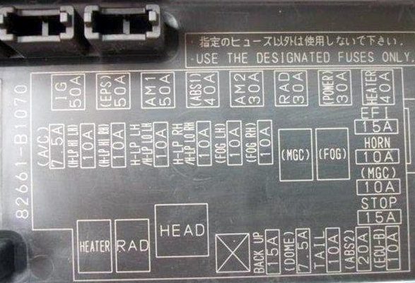
Diagram

Appointment
| 1 | 50A IG – Power windows. Glass wipers and washers. Fog lights. |
| 2 | 50A EPS – Electric power steering |
| 3 | 40A AM1 |
| 4 | 40A ABS – Anti-lock braking system |
| 5 | 30A AM2 – Starting system |
| 6 | 30A RAD – Electric fan drive |
| 7 | 30A POWER – Power windows. Connector for additional equipment |
| 8 | 40A HEATER – Manual air conditioner and air ionizer |
| 9 | 7,5А А / С – Air conditioner |
| 10 | 10A H-LP HI LH – Left headlight (high beam) |
| 11 | 10A H-LP HI RH – Right headlight (high beam) |
| 12 | 10A H-LP LO LH – Left headlight (low beam |
| 13 | 10A H-LP LO RH – Right headlight (low beam) |
| 14 | 10A FOG LH – Fog lights (left) |
| 15 | 10A FOG RH – Fog lights (right) |
| 16 | 15A EFI – Engine Management |
| 17 | 10A HORN – Signal |
| 18 | 10A MGC – Air conditioner |
| 19 | 15A STOP – Stop lights |
| 20 | 15A BACK UP – Reverse |
| 21 | 15A DOME – Interior lighting |
| 22 | 10A TAIL – Instrument cluster, clock, dimensions |
| 23 | 20A ABS 2 – ABS |
| 24 | 10A ECU-B – automatic transmission, backlight |
| R1 | Heater relay |
| R2 | Audio system relay |
| R3 | Headlight relay |
| R4 | Air conditioner relay |
| R5 | Fog lamp relay. |
If you have something to add – write in the comments.