The second-generation Toyota Raum was produced in 2003, 2004, 2005, 2006, 2007, 2008, 2009, 2010, and 2011 under the designation XZ20. During this time, the model received a facelift. In this article, you will find information on the location of the electronic control units, a detailed description of the Toyota Raum 2 fuses and relays, with block diagrams, their locations, and photo examples. We will highlight the fuse responsible for the cigarette lighter.

The locations of the units and their design may differ from those shown and depend on the year of manufacture and the level of electrical equipment.
Contents
Passenger compartment
Boxes arrangement
General layout of electronic control units

Assignment
- Immobilizer Control Unit
- Headlight Range Adjustment Unit (models from 08/2005)
- Camera Controller (models before 12/2006)
- Remote Control Central Locking Receiver
- SMART KEY Receiver
- SMART KEY Electronic Unit
- Wiper Blade Defroster Relay (models before 12/2006)
- Engine Control Unit
- SRS Electronic Control Unit
- Fog Light Relay (models from 12/2006)
- Wiper Blade Defroster Relay (models from 12/2006)
- Under-Dashboard Mounting Block
- Connector (CAN #7) (models from 12/2006)
Fuse Box
Located under the dashboard on the driver’s side.

Check the element designations against your diagrams on the block cover.
Diagram from the box cover

Photo example of execution

Diagram

Designation
| 1 | 10A TAIL – Side Marker Lights, Marker Lights, Tail Lights, License Plate Lights, Multiport Fuel Injection System / Sequential Multiport Fuel Injection System |
| 7,5A PANEL2 – Engine immobilizer system, entry and start system, front fog lamp, lighting, light reminder, multi-mode manual transmission, rear fog lamp, start, steering lock, taillight, wireless door lock control | |
| 2 | 7,5A PANEL1 – Lighting, dashboard lighting control, counter and sensor |
| 3 | 7,5A A / C – Heated rear window, air conditioning system |
| 4 | 20A D DOOR – Window regulator |
| 5 | 20A RL DOOR – Rear passenger power window (left side) |
| 6 | 20A RR DOOR – Rear passenger power window (right side) |
| 7 | – |
| 8 | 15A CIG – Cigarette lighter, Socket |
| 9 | 7,5A ACC – Door locking system, outside rearview mirrors, audio system |
| 10 | – |
| 11 | 10A ID / UP / MIR HTR – Multiport fuel injection system / sequential multiport fuel injection system / Heated mirrors |
| 12 | |
| 13 | |
| 14 | 7,5A RR FOG – Rear fog lights |
| 15 | 7.5A IGN – Multiport fuel injection system / sequential multiport fuel injection system, engine immobilizer system, SRS airbag system, front passenger classification system |
| 16 | 7,5A MET – Instruments and sensors |
| 17 | 15A P S-HTR – Heated seat |
| 18 | 15A D S-HTR – Heated seat |
| 19 | 20 / 25A WIP – Wiper |
| 20 | 15A RR WIP – Rear wiper |
| 21 | 15A WSH – Windshield washer |
| 22 | 10A ECU-IG – Daytime Running Light System, Antilock Braking System, Electric Power Steering System, Power Windows, Door Lock System, Anti-theft System, Electric Cooling Fan |
| 23 | 10A GAUGE – Charging System, Turn Signals, Hazard Lights, Tail Lights, Dashboard Lighting Control, Gear Shift Lock System, Heated Rear Window, Air Conditioning System, Automatic Transmission System |
| 24 | 7,5A OBD2 – On-board diagnostic system |
| 25 | 10A STOP – Stop Lamps, Top Mounted Stop Lamp, Multiport Fuel Injection System / Sequential Multiport Fuel Injection System, Shift Lockout System, Antilock Braking System |
| 26 | – |
| 27 | 25A D / L – Door lock system |
| 28 | 10A TAIL – Side marker lights, parking lights, tail lights, license plate light, multipoint fuel injection system/sequential multipoint fuel injection system |
| 29 | 7.5A RR FOG – Rear fog lights |
| 30 | 15A FR FOG – Front fog lights |
| 31 | 25A AM1 – Multiport fuel injection system / sequential multiport fuel injection system |
For the cigarette lighter, there is a fuse number 8, 15A, marked on the lid as CIG.
The individual elements are attached to the top of the unit.

Diagram

Appointment
| F1 | 30А Bodywork ECU / Window Electrics |
| F2 | 30/40А Power supply for direction indicator relay / Heated rear window, fuse: “MIR HTR” |
| F3 | 30А Heated seats |
| R1 | Relay – turn signal interrupter |
| R2 | Heater relay |
| R3 | Relay “IG1” – ignition system |
Diagram

Assignment
- ACC relay
- Ignition system relay
- Heater relay
- Rear fog lamp relay
- Front fog lamp relay
- 1) 30A Bodywork ECU / Window Electrician (POW) 2) 30 / 40A Heated rear window DEF, fuse: “MIR HTR”
Engine compartment
Boxes arrangement
Location

Purpose
- ABS Relay Box
- Relay Box #2
- Fuse Box
- Main Fuse and Relay Box
Fuse and relay box
This unit is located on the left side of the engine compartment, next to the battery.
Photo

Check your diagram on the box cover
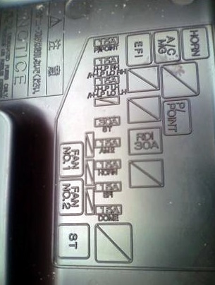
Diagram
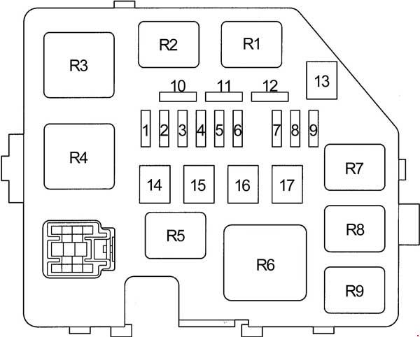
Designation
| 1 | 15A DOME – Clock, instrument cluster, dual lock, headlights, interior lighting, warning buzzer, multi-information display, audio system, door lock control unit |
| 2 | 15A EFI – Engine control unit, immobilizer, transmission control unit |
| 3 | 15A HORN – Sound signal |
| 4 | 15A AM2 – Charging system, instrument cluster, engine control unit, immobilizer, gearbox control unit, multi-information display, SRS airbag system, ignition system |
| 5 | 15A RAD No.1 – Audio system |
| 6 | – |
| 7 | 10A H − LP LH – Left headlight, headlight range control |
| 8 | 10A H − LP RH – Left headlight, headlight range control |
| 9 | 10A ST – Starting System |
| 10 | Spare fuse |
| 11 | Spare fuse |
| 12 | Spare fuse |
| 13 | – |
| 14 | – |
| 15 | 30A RDI – Cooling fan |
| 16 | 50A HTR SUB1 – Auxiliary heater (PTC) |
| 17 | – |
| Relay | |
| R1 | Cooling fan |
| R2 | Cooling fan |
| R3 | Starter |
| R4 | – |
| R5 | Power socket |
| R6 | Auxiliary heater (PTC) |
| R7 | EFI |
| R8 | A / C Compressor Clutch |
| R9 | Sound signal |
Additional box
Diagram

Appointment
| 1 | 10А H-LP HI RH – Headlights (daytime running lights) |
| 2 | 10А H-LP HI LH – Instrument cluster, headlights (daytime running lights) |
| Relay | |
| R1 | Headlights |
| R2 | Dimmer (DIM) |
| R3 | – |
ABS box
Diagram

Assignment
- 1 – ABS fuse # 3 (models without VSC); no (models with VSC)
- A – no (models without VSC); ABS MTR relay (models with VSC)
- B – ABS MTR relay (models without VSC); ABS CUT relay (models with VSC)
- C – ABS SOL relay (models without VSC); no (models with VSC).
Power fuse box
It is located on the positive terminal of the storage battery and is made in the form of high-power fuse-links.
Diagram

Designation
- 60А MAIN – Fuses: “EFI”, “DOME”, “HORN”, “ST”, “AM2”, “H − LP LH”, “H − LP RH”, “H − LP LH (HI)”, ” H − LP RH (HI) ”,“ H − LP LH (LO) ”,“ H − LP RH (LO) ”
- 80A – “START / STOP” system
- ALT 100 / 120A – Fuses: “ECU-B”, “TAIL”, “D / L”, “OBD”, “RDI”, “AM1”, “HAZ”, “HTR”, “HTR-SUB1″, ” POWER ”,“ STOP ”,“ DEF ”, Charging system
- 60A ABS – ABS
If you have any questions, ask in the comments. Together we will try to answer them.