The 2nd generation Honda Stepwgn was produced in 2001, 2002, 2003, 2004 and 2005 with designations RF3 – RF8. During this time, the model has been updated. In this material you will find a description of fuses and relays Honda Stepvagon 2 with fuse box diagrams, their locations and photographs. Select the cigarette lighter fuse.

The purpose of the fuses and relays may differ from the one shown and depends on the year of manufacture and the level of equipment of your vehicle.
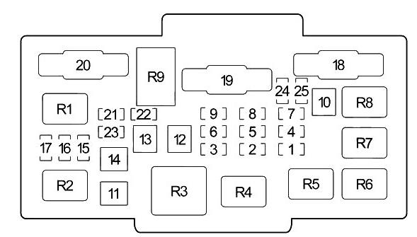
Passenger compartment
In the cabin, the main fuse and relay box is located at the bottom of the instrument panel, on the driver’s side. To access, remove the protective cover.
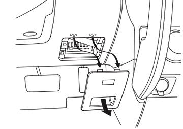
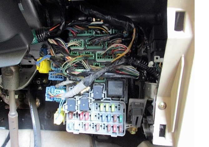
Photo example
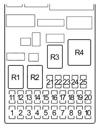
Diagram
Designation
| 1 | 15A Ignition coils |
| 2 | 10A Rear outlet |
| 3 | 10A Daytime running lights, body electronics (Multiplex) |
| 4 | 10A Alternator, Camshaft Position Sensor (CMP) A, Cruise Control, VSA OFF, Electrical Load Sensor (ELD), Gasoline Vapor Emission System (EVAP), Intake Manifold Valve (IMT), Secondary Oxygen Sensor (HO2S), Speed Sensor (VSS) (M/T), Vehicle Stability Control (VSA), Variable Intake Manifold Length Valve (IMRC), ABS Control Unit (’03-’04) |
| 5 | – |
| 6 | 7.5A Air Fuel Ratio (A/F) Sensor Relay, Sunroof Relay, Power Window Control Module, Power Window Relay |
| 7 | 20A Sunroof relay |
| 8 | 7.5A Instrument cluster, body electronics (Multiplex), gear selector lock, audio system |
| 9 | 7.5A Front passenger seat occupied detection system, front passenger weight sensor, rear wiper, wiper switch |
| 10 | 7.5A Reverse lamp relay (A/T), reverse lamp switch (M/T), instrument cluster, key receiver, body electronics (Multiplex), anti-theft system, ABS control unit (’02), selector lock relay gearboxes (’02-’04) |
| 11 | – |
| 12 | 7.5A Daytime running lights (DRL), body electronics (Multiplex) |
| 13 | 10A Airbag control unit (SRS) |
| 14 | 10A A/C Compressor Clutch Relay, A/C Fan Relay, Heater Relay, Power Mirrors, Cooling Fan Relay, Heated Rear Window Relay, Air Recirculation Mode, Heated Seat Relay, Heater Control Module |
| 15 | 15A ’05-’06: Front Power Outlet Relay |
| 20A ’02-’04: Air Fuel Ratio (A/F) Sensor Relay | |
| 16 | 20A Seat heating relay |
| 17 | 15A Fuel Pump, Engine Control Module/Powertrain Control Module (ECM/PCM), Front Passenger Airbag Deactivated Indicator, Immobilizer, Engine Control Module Main Relay (PGM-FI Main) 2, Airbag Control Module (SRS) |
| 18 | 15A Audio system (’05-’06), front outlet, rear outlet |
| 19 | 7.5A Hazard and direction indicators |
| 20 | 20A Front wiper and washer, body electronics (Multiplex) |
| 21 | – |
| 22 | 20A Front passenger window |
| 23 | 20A Driver window regulator |
| 24 | 20A Rear left power window |
| 25 | 20A Rear right power window |
| Relay | |
| R1 | Starter (A/T) |
| R2 | marker light |
| R3 | Power windows |
| R4 | Hazard and direction indicators |
Engine compartment
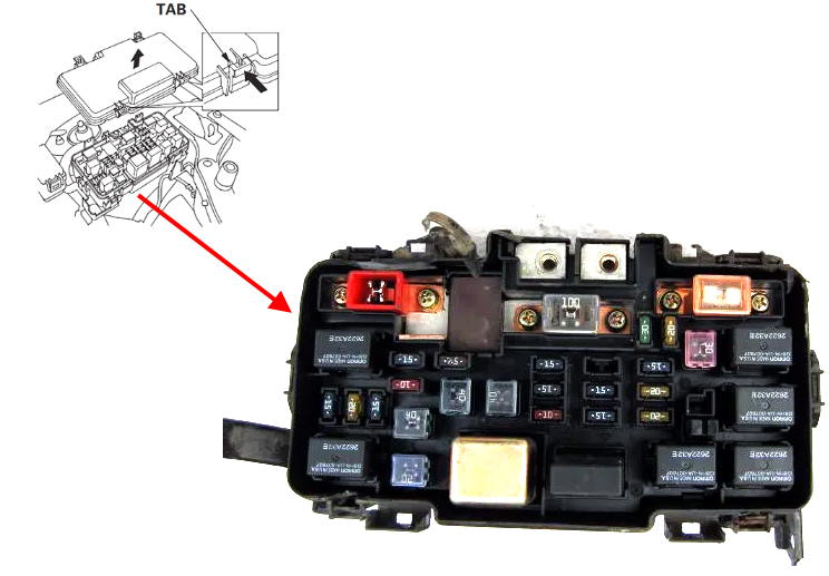
The main fuse and relay box is located under the hood next to the battery. To access, remove the protective cover of the unit. The block itself will look something like this.
Diagram
Appointment
| 1 | 20A A/C Compressor Clutch Relay, A/C Condenser Fan Relay |
| 2 | 30A 2005-2006: Air-Fuel Ratio (A/F) Sensor Relay, Daytime Running Lights (DRL) Relay, PGM-FI Main Relay 1, Ignition Coil Relay, Fuses (Engine Compartment): 31, 32, 33, 34 |
| 15A 2002-2004: Tail light relay | |
| 3 | 15A Interior Lights, Front Dome Light, Ignition/Key Light, Rear Dome Light, Rear Wiper Control Unit, Spotlights, XM Receiver A Connector, Spotlights |
| 4 | 20A Radiator fan relay |
| 5 | 15A Hazard switch, trailer light connector |
| 6 | 15A 2005-2006: Tail light relay |
| 10A 2002-2004: Main Relay 1 PGM-FI | |
| 7 | 15A Stop Lamp (Brake Pedal Position Switch), Horn Relay |
| 8 | 15A 2005-2006: Throttle Actuator Control Module Relay |
| 9 | 10A Audio System, Reversing Light, Data Link Connector (DLC), Sensor Assembly, Immobilizer Control Unit, Keylees Receiver Unit, Multiplex Control Unit |
| 10 | 30A Vehicle Stability Control (VSA) / ABS Modulator Control Unit |
| 11 | 20A Rear defroster relay |
| 12 | 40A Fan motor relay |
| 13 | 40A Power window relay, fuses (passenger compartment): 7, 23 |
| 14 | 40A Fuses (in passenger compartment): 2, 3, 5, 15, 16 |
| 15 | 20A Left headlight, daytime running light (DRL) control unit, sensor assembly, |
| 16 | 20A Power door interlock, multiplex control unit |
| 17 | 20A Right headlight, daytime running light (DRL) control unit |
| 18 | 30A Vehicle Stability Control (VSA) / ABS Modulator Control Unit |
| 19 | 100A Battery, power distribution |
| 20 | 50A Ignition switch |
| 21 | — |
| 22 | — |
| 23 | — |
| 24 | — |
| 25 | — |
| Relay | |
| R1 | Left headlight |
| R2 | Right headlight |
| R3 | Fan motor |
| R4 | Rear window heating |
| R5 | A/C Compressor Clutch |
| R6 | Radiator fan |
| R7 | Horn |
| R8 | Air conditioning condenser fan |
| R9 | Electrical Load Detector (ELD) Unit |