The 4th generation Honda Accord was produced in 1989, 1990, 1991, 1992 and 1993 with 1.8 2.0 and 2.2 liter petrol engines. In this article you will find a description of the Honda Accord 4 fuses and relays with fuse box diagrams, photographs and their locations. Select the fuse responsible for the cigarette lighter.

The purpose of the fuses and relays may differ from the one shown and depends on the year of manufacture, the region of delivery and the level of equipment of your car.
Contents
Passenger compartment
Location
Layout

Assignment
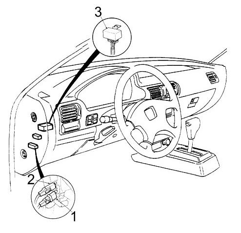
- Fuse and relay box
- Cooling Fan Control Unit/Timer
- Diagnostic connector (DLC)
Fuse and relay box
In the cabin, the main fuse and relay box is located under the instrument panel, on the pillar near the driver’s left foot and is closed with a protective cover.

Diagram

Designation
| 1 | – |
| 2 | 10A Instrument cluster, gear indicator, shift lock solenoid, airbag indicator, reversing lamps, speed sensor, turn signal relay, clock, automatic seat belts, body electronics unit (ICU) |
| 3 | 15A Engine control module (PGM-FI) relay, fuel pump, exhaust system, voltage regulator, cooling fan timer, charge indicator, transmission control module, electrical load sensor (ELD), engine mount control module, idle air valve |
| 4 | 10A ’92-’93: Airbag control unit |
| 5 | – |
| 6 | – |
| 7 | 7.5A Cruise control, cruise control control unit |
| 8 | 7.5A ’90-’92: Hatch |
| 10A ’93: Sunroof, rear window washer, power mirrors | |
| 9 | 30A Front wiper and washer |
| 10 | – |
| 11 | – |
| 12 | 7.5A A/C compressor clutch relay |
| 13 | 7.5A Cooling fan timer, heater control panel, ABS, air recirculation system |
| 14 | 7.5A Starter signal (automatic transmission), instrument cluster |
| 15 | 7.5A Daytime running light relay |
| 16 | Audio system, cigarette lighter |
| Relay | |
| R1 | Turn Signals/ Hazard Signals |
| R2 | Heater |
| R3 | Rear window heating |
| R4 | Moonroof (opening) |
| R5 | Moonroof (closing) |
The number 16 fuse is responsible for the cigarette lighter.
Additional elements
Diagram

Allocation
- Horn relay
- Cigarette lighter relay
- Engine control unit relay (PGM-FI)
Engine compartment
Location
Layout

Appointment
- Main fuse and relay box
- Additional relay box
Fuse and relay box
Under the hood, the main fuse and relay box is on the right side.
Photo example

Check the decoding of the elements with your diagrams on the cover of the blocks.
Take the diagram from the cover

Diagram

Assignment
| 15 | 100A ’90-’91: Main fuse |
| 80A ’92-’93: Main fuse | |
| 16 | 40A Sedan, Coupe: Heated rear window relay |
| 30A Wagon: Heated rear window relay | |
| 17 | 30A Heater relay |
| 18 | 50A Ignition switch |
| 19 | 20A Left headlight |
| 20 | 20A Right headlight, high beam indicator |
| 21 | 15A ’90-’91: Cooling Fan |
| 20A ’92-’93: Cooling Fan Relay | |
| 22 | 30A ’90-’91: Automatic seat belt control unit |
| 10A ’92-’93: Daytime running lights | |
| 23 | 30A ’90-’91: Automatic seat belt control unit |
| 10A ’93: Audio Amplifier | |
| 24 | 20A Rear right power window |
| 25 | 20A Rear left power window |
| 26 | 20A Front right power window |
| 27 | – |
| 28 | 20A Front left power window |
| 29 | 20A ’90-’91: Luke |
| 30A ’92-’93: Hatch | |
| 30 | 20A Horn, stop lamps, ignition key interlock solenoid |
| 31 | – |
| 32 | 20A Central locking |
| 33 | 10A Engine control unit relay (PGM-FI) |
| 34 | 15A A/C fan, engine cooling fan timer |
| 35 | 10A Direction indicators and hazard warning lights |
| 36 | – |
| 37 | 15A Interior lighting, cigarette lighter, antenna, ignition switch illumination, body electronics unit (ICU) |
| 38 | 15A Parking lights, glove box light, license plate light, optional “C” connector, instrument panel light, backlight dimmer, body electronics unit (ICU) |
| 39 | 7.5A Engine control unit (PGM-FI ECU), transmission control unit, audio system, clock, automatic seat belts |
| Relay | |
| R1 | Headlights |
| R2 | Power windows |
| R3 | Dimmer |
| R4 | Cooling fan |
Relay box
Diagram

Designation
- R1 – Air conditioning compressor clutch
- R2 – Air conditioning fan
If you know how to make the material better – write in the comments.
 FuseAndRelay.com