Updated Ford Transit 8G was produced in 2020, 2021, 2022, 2023 and 2024. Ford Transit Custom / Tourneo Custom provides the mid-size light-duty Ford Transit series. In this post you will find a designation of the Ford Transit 2020 – 2024 fuse and relay boxes, boxes diagrams and their location. Also we highlight the fuse responsible for the cigarette lighter.

The purpose of the fuses and relays may differ from that shown and depends on the year of manufacture and the level of electrical equipment of your vehicle.
Contents
Passenger compartment
Inside the Ford Transit mk8 there are 3 fuse and relay boxes. 2 under the dashboard on the driver’s side and one behind the back of the driver’s seat.
Dashboard fuse box
Remove the protective cover for access.
Fuse box
Located under the panel on the left side.

Diagram

Assignment
| 1 | Not used |
| 2 | 10A — Power inverter |
| 3 | 7.5A — Power exterior mirrors |
| 4 | 20A — Not used |
| 5 | Not used |
| 6 | 10A — Anti-theft alarm horn |
| 7 | 10A — Not used |
| 8 | 5A — Telematics control unit module |
| 9 | 5A — Rear air conditioning |
| 10 | Not used |
| 11 | Not used |
| 12 | 7.5A — Climate control |
| 13 | 7.5A — Steering column, Instrument cluster, Data link connector |
| 14 | 15A — Battery energy control module (MHEV) |
| 15 | 15A — SYNC 3 module |
| 16 | Not used |
| 17 | 7.5A — Tachograph |
| 18 | 7.5A — Not used |
| 19 | 5A — Battery back-up sounder |
| 20 | 5A — Ignition switch |
| 21 | 5A — Positive temperature coefficient heater control |
| 22 | 5A — Pedestrian alert control module |
| 23 | 30A — Not used |
| 24 | 30A — Not used |
| 25 | 20A — Driver door module |
| 26 | 30A — Passenger door module |
| 27 | 30A — Not used |
| 28 | 30A — Gear shift module (BEV), Navigation display (diesel) |
| 29 | 15A — Not used |
| 30 | 5A — Not used |
| 31 | 10A — Data link connector, Remote key receiver |
| 32 | 20A — Radio, Telematics module |
| 33 | Not used |
| 34 | 30A — Tachograph, Message center, PTC heater, Lane keeping system camera, Parking aid, Steering column |
| 35 | 5A — |
| 36 | 15A — Lane keeping system camera, Steering column control moduleб Parking aid |
| 37 | 20A — Not used |
| 38 | 30A — Power windows |
Fuse and relay box
Located under the panel on the right side of the side.

Diagram

Designation
| 1 | 5A — USB port |
| 2 | Not used |
| 3 | 5A — USB port |
| 4 | Not used |
| 5 | Not used |
| 6 | Not used |
| 7 | Not used |
| 8 | Not used |
| 9 | 10A — Heated exterior mirrors |
| 10 | Not used |
| 11 | Not used |
| 12 | Not used |
| 13 | Not used |
| 14 | Not used |
| 15 | Not used |
| 16 | 5A — Rain sensor |
| 17 | Not used |
| 18 | 20A — Rear window wiper motor |
| 19 | Not used |
| 20 | Not used |
| 21 | 20A — Heated rear window |
| 22 | 20A — Heated rear window |
| 23 | 20A — Auxiliary power point |
| 24 | 20A — Auxiliary power point |
| 25 | Not used |
| 26 | 25A — Windshield wiper motor |
| 27 | Not used |
| 28 | Not used |
| 29 | Not used |
| 30 | 30A — Power running boards |
| 31 | Not used |
| 32 | Not used |
| 33 | Not used |
| 34 | Not used |
| 35 | 5A — Trailer tow module |
| 36 | Not used |
| 37 | Not used |
| 38 | Not used |
| 39 | Not used |
| 40 | Not used |
| 41 | Not used |
| 42 | 40A — Starter relay |
| 43 | Upfitter relay |
| 44 | 40A — Starter relay |
| 45 | 10A — Upfitter interface module |
| 46 | 15A — Trailer tow module |
| 47 | 5A — Fuel fired heater |
| 48 | Not used |
| 49 | 10A — Brake pedal switch |
| 50 | Not used |
| 51 | Not used |
| 52 | 30A — Driver power seat |
| 53 | 60A — Battery |
| 54 | 60A — Power inverter |
| 55 | 50A — Body control module |
| 56 | Not used |
| 57 | Not used |
| 58 | 10A — Upfitter interface, Secondary junction box, Rear climate control |
| 59 | 10A — Front view camera, Rear view camera, Adaptive cruise control module, Blind spot information system |
| 60 | 10A — Reductant dosage control module |
| 61 | 7.5A — Tachograph |
| 62 | 15A — Enhanced cut off relay system module |
| 63 | 20A — Auxiliary power point |
| 64 | Not used |
| 65 | Not used |
| 66 | 10A — Camper, Load shed relay |
| 67 | Not used |
| 68 | Not used |
| 69 | 5A — Steering wheel module |
| 70 | Not used |
| 71 | 10A — Heated seats |
| 72 | 10A — Heated seats |
| 73 | 20A — Adaptive front lighting module, Headlamp leveling |
| 74 | Not used |
| 75 | 20A — Engine compartment fuse box |
| 76 | 10A — Power sliding door control switch |
| 77 | 5A — Headlamp switch |
| 78 | 10A — Power sliding door latch switch |
| 79 | Not used |
| 80 | 5A — Starter relay |
| 81 | 40A — Trailer tow module |
| 82 | 30A — Power sliding door |
| 83 | Not used |
| 84 | 50A — Body control module |
| 85 | 30A — Power sliding door |
| 86 | 50A — Body control module |
Passenger side fuse box
Location

Diagram

Description
| 1 | 40A — Auxiliary switch 1 |
| 2 | 40A — Auxiliary switch 2 |
| 3 | 20A — Beacon switch |
| 4 | 20A — Ignition |
| 5 | 10A — Direction indicators |
| 6 | Not used |
| 7 | Not used |
| 8 | 10A — Interior lighting |
| 9 | 15A — Two-way radio connector |
| 10 | 5A — Ignition |
| 11 | 10A — Ignition |
| 12 | 20A — Touchscreen |
| 13 | 5A — Power mode relay |
| 14 | 5A — Ignition |
| 15 | 20A — Power supply |
| 16 | 20A — Beacon relay |
| 17 | 40A — Auxiliary switch 1 relay |
| 18 | 40A — Auxiliary switch 2 relay |
| 19 | 20A — Ignition relay |
| 20 | 20A — Left direction indicator relay |
| 21 | 20A — Smart regenerative charge inhibit relay |
| 22 | 20A — Interior lamps relay |
| 23 | 20A — Right direction indicator relay |
| 24 | 40A — Auxiliary power 4 relay |
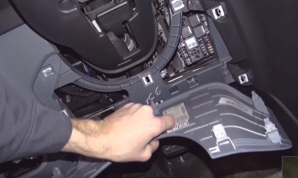
Fuse box behind the driver’s seat
The high current fuse box is under the driver seat. To access remove the trim panel.

Photo for example

Diagram

Allocation
- 125A – Body control module.
- 80A – Electronic power assist steering.
- 150A – Auxiliary heater.
- Not used.
- Not used.
- 150A – Passenger compartment fuse box.
- 60A – Camper.
- Battery. Starter motor.
- 470A – Alternator.
- 300A – Engine compartment fuse box.
- 250A – Direct current/Direct current converter – MHEV.
- 150A – Driver compartment fuse box.
- Load shed relay.
- 180A – Auxiliary power point 1.
- 60A – Auxiliary power point 2.
Identifying fuse types.

Appointment
- A – Micro 2.
- B – Micro 3.
- C – Maxi.
- D – Mini.
- E – M Case.
- F – J Case.
- G – J Case Low Profile.
- H – Slotted M Case
Engine compartment
Location

Diagram

Decoding
| 1 | 50A — Wipers |
| 2 | 20A — All-wheel drive |
| 3 | 40A — Right-hand heated windshield element |
| 4 | 15A — Rear window washer pump |
| 5 | — |
| 6 | — |
| 7 | 40A — Front blower motor |
| 8 | 40A — Left-hand heated windshield element |
| 9 | 15A — Not used (spare) |
| 10 | 5A — Battery energy control module (MHEV) |
| 11 | 40A — USB port / Auxiliary power point |
| 12 | 20A — Horn |
| 13 | 10A — Selective catalytic reduction system |
| 14 | 10A — Battery energy control module / Powertrain control module |
| 15 | — |
| 16 | — |
| 17 | 10A — Right-hand high-intensity discharge headlamps |
| 18 | 40A — Rear window defroster |
| 19 | 20A — Not used (spare) |
| 20 | 10A — Power folding mirrors |
| 21 | 15A — Vehicle power 4 |
| 22 | 40A — Rear blower motor |
| 23 | 20A — Fuel pump |
| 24 | 40A — Not used (spare) |
| 25 | 40A — Auxiliary power points |
| 26 | 10A — Left-hand high-intensity discharge headlamps |
| 27 | 40A — Selective catalytic reduction system |
| 28 | 20A — Vehicle power 1 |
| 29 | 40A — Fuel filter heater |
| 30 | 7.5A — Coolant pump |
| 31 | 5A — Anti-lock brake system |
| 32 | 15A — Transmission control module |
| 33 | 30A — Starter motor |
| 34 | 15A — Selective catalytic reduction system |
| 35 | 15A — Vehicle power 2 |
| 36 | 5A — Belt integrated starter generator (MHEV) |
| 37 | 5A — Powertrain control module |
| 38 | 60A — Glow plug control module |
| 39 | 15A — Selective catalytic reduction system |
| 40 | 10A — Vehicle power 3 |
| 41 | 10A — Glow plug controller |
| 42 | 15A — Transmission control unit |
| 43 | 60A — Anti-lock brake system pump |
| 44 | 25A — Cooling fan |
| 45 | 30A — Trailer socket |
| 46 | — |
| 47 | — |
| 48 | 50A — Cooling fan |
| 49 | 15A — Nitrogen oxides sensor |
| 50 | 5A — Closed crankcase ventilation heater |
| 51 | 10A — Air conditioning clutch |
| 52 | 50A — Cooling fan |
| 53 | 5A — Active tensioner (MHEV) |
| 54 | 20A — Not used (spare) |
| 55 | 25A — Transmission oil pump |
| 56 | 25A — Fuel-fired booster heater |
| 57 | 25A — Anti-lock brake system with electronic stability control |
| 58 | 30A — Trailer socket |
| 59 | Cooling fan relay |
We have posted a video on our YouTube channel. Watch and subscribe.
Want to help complete the post? Write your questions or comments in the comments.