The 9th generation Mitsubishi Galant was produced in 2004, 2005, 2006, 2007, 2008, 2009, 2010, 2011 and 2012. In our material, we will show a description of the 9th generation Mitsubishi Galant fuses and relays with box diagrams and their locations. Highlight the cigarette lighter fuse.

There may be a difference in the presented material and your performance. Check the designation with your diagrams or other technical documentation.
Wrong generation or diagram not suitable?
[ Description Galant 8 ]
[ Description Galant 7 ]
Contents
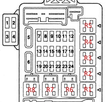
Passenger compartment fuse box
Located at the end of the dashboard behind the protective cover.

For example

Legend of a diagram from the box cover

Diagram
Protected components
| 1 | Reserve |
| 2 | Reserve |
| 3 | 30A Audio amplifier |
| 4 | 20A Roof hatch assy |
| 5 | 30A Heated rear window, Interference suppression capacitor |
| 6 | 30A Heater fan motor |
| 7 | Reserve |
| 8 | Reserve |
| 9 | 15A Connector for connecting additional electrical equipment |
| 10 | 15A Diagnostic socket, Central locking, ETACS control unit |
| 11 | ETACS control unit |
| 12 | Reserve |
| 13 | 7.5A Electrochromic rear-view mirror; |
| 14 | 7.5A Electric drives for side rear-view mirrors |
| 15 | Reserve |
| 16 | 15A Cigarette lighter |
| 17 | 7.5A Fuel pump relay; engine and automatic transmission control unit |
| 18 | Reserve |
| 19 | 7.5A Heaters for side rear-view mirrors |
| 20 | 7.5A Relay |
| 21 | Reserve |
| 22 | 7.5A Rear combination lights, Automatic transmission controls |
| 23 | 7.5A Multifunction display, Steering column switch, Control units (ABS, ETACS, SRS) |
| 24 | 10A Ignition coil |
The fuse number 9, 15A, is responsible for the cigarette lighter.
Relay
- Fuel pump relay (1)
- Socket relay for connecting additional equipment
- Fuel pump relay (2)
- Front seat heating relay
- Rear fog lamp relay
- Relay for electro glass lifts
- Heater blower motor relay
- Heated rear window relay
Engine compartment fuses and relays boxes
Located on the left side of the engine compartment next to the battery.

Green section – electronic control unit for lighting.
Main box
Diagram

Assignment
| 1 | 80A Battery |
| 2 | 30 / 50A Cooling fan motor |
| 3 | 60A ABS system |
| 4 | 40A Ignition Lock Circuit |
| 5 | 30A Power windows |
| 6 | 15A Fog lights |
| 7 | 15A / 20A Heated seats |
| 8 | 20A Buzzer |
| 9 | 20A Engine management system |
| 10 | 10A A / C Compressor Electromagnetic Clutch |
| 11 | 15A Stop lights |
| 12 | 10A Rear fog lamps |
| 13 | 7.5A Generator |
| 14 | 10A Alarm |
| 15 | 20A Electronic gearbox control unit |
| 16 | 10A High beam, right headlight |
| 17 | 10A High beam left headlight |
| 18 | 10A Low beam, right headlight |
| 19 | 10A Low beam left headlight |
| 20 | 7,5A Dimensions right |
| 21 | 7,5A Dimensions, left |
| 22 | 10A Interior lamps |
| 23 | 10A Audio system |
| 24 | 15A fuel pump |
| 25 | 30A Glass cleaner |
Relay
- Fog lamp relay
- Windshield heater relay
- Accessory Power Connector Relay
- Horn relay
- Fog lamp relay
- Cooling fan motor relay
Relay box
Diagram

Functions
- A / C compressor electromagnetic clutch relay
- Engine control relay
- Transmission electronic control unit relay
- Ignition relay
- Throttle control unit relay
- Reserve
- Reserve
Main fuse
The main power fuse in the form of a high-power fusible link is located on the positive terminal of the battery.

Separately, outside the units shown, additional relays can be attached, for example: the relay for the condenser fan motor and the air conditioner fan and the audio system fuse.
For mitsubishi galant 2008, starter relay is not shown in the diagrams.