The Mazda CX-30 was produced in 2019, 2020, 2021, 2022, 2023, 2024, 2025, and 2026. In this guide, you will find a description of the fuses and relays for the Mazda CX-30, including fuse box diagrams, their locations, and photographic examples. We will also identify the specific fuse responsible for the cigarette lighter.
The design of the fuse and relay boxes and the assignment of fuses and relays may differ from that shown and depends on the year of manufacture and the level of electrical equipment in your vehicle.
Passenger compartment
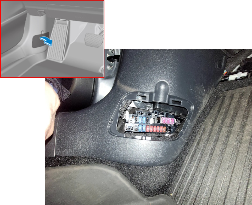
Inside the vehicle, the fuse box is located at the base of the pillar on the driver’s side; to access it, you must remove the protective cover.
Diagram
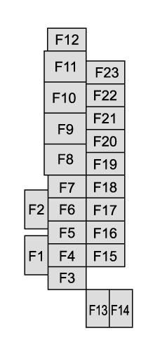
Description
| F1 | Not used |
| F2 | Not used |
| F3 | Not used |
| F4 | 15 A — Power door locks (driver’s door) |
| F5 | 15 A — Power door locks (passenger’s door) |
| F6 | Not used |
| F7 | 25 A — Power liftgate (Some Models) |
| F8 | Not used |
| F9 | 30 A — Power windows (driver’s door) |
| F10 | 30 A — Power windows (passenger’s door) |
| F11 | 30 A — Power driver’s seat (Some Models) |
| F12 | Not used |
| F13 | 15 A — Audio |
| F14 | Not used |
| F15 | 15 A — Liftgate lock |
| F16 | 15 A — Illumination |
| F17 | 10 A — Stop lights |
| F18 | 10 A — Back-up lights |
| F19 | 10 A — Rear turn signal lights |
| F20 | 10 A — Tail lights |
| F21 | 10 A — Tail lights |
| F22 | 7.5 A — Electric steering lock |
| F23 | Not used |
Engine compartment
The main fuse and relay box is installed under the hood on the left-hand side and is also covered by a protective lid.
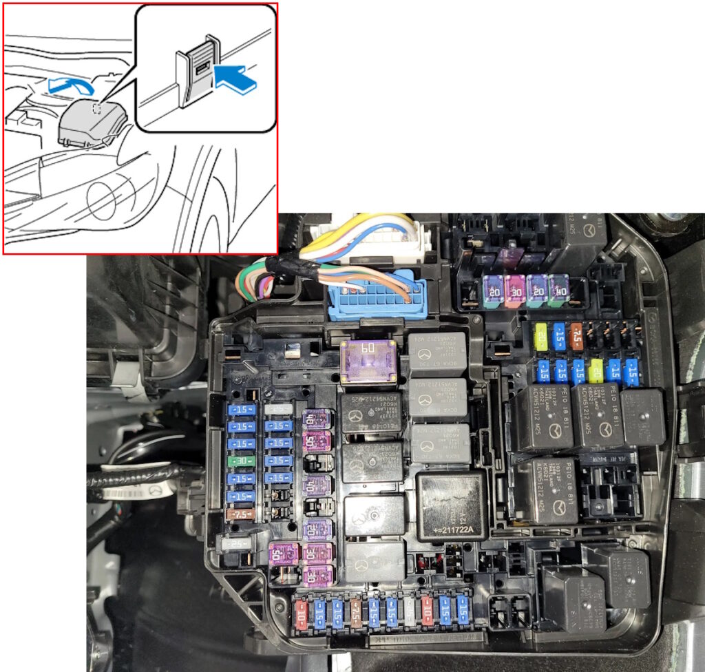
Check the purpose of the components against the diagram on the back of the unit cover.
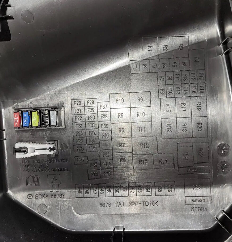
Diagram

Designation
Fuses
| F1 | Not used |
| F2 | 20 A — Windscreen wiper de-icer |
| F3 | 30 A — Engine control system 20 A / 30 A — Injector |
| F4 | 20 A — S-VT |
| F5 | 40 A — Engine control system |
| F6 | 20 A — S-VT |
| F7 | 15 A — Fuel warmer 20 A — Fuel pump |
| F8 | 15 A — Engine control system |
| F9 | 15 A — Transmission control system |
| F10 | 15 A — Engine control system |
| F11 | 7.5 A — Air conditioner |
| F12 | 15 A — Engine control system |
| F13 | 15 A — NOx sensor |
| F14 | 20 A — Front seat warmer |
| F15 | 20 A — Headlight washer |
| F16 | 15 A — For protection of various circuits |
| F17 | Not used |
| F18 | 15 A — Accessory sockets |
| F19 | 60 A — Power steering system |
| F20 | 15 A — Headlight (LH) 1 |
| F21 | 15 A — Headlight (RH) 1 |
| F22 | 15 A — Keyless system |
| F23 | 30 A — ABS, Dynamic stability control system |
| F24 | 15 A — Headlight (LH) 2 |
| F25 | 15 A — Headlight (RH) 2 |
| F26 | 7.5 A — On board diagnostics |
| F27 | 25 A — For protection of various circuits |
| F28 | 25 A — For protection of various circuits |
| F29 | 15 A — Windscreen washer |
| F30 | 15 A — Accessory sockets, cigarette lighter |
| F31 | 15 A — Horn |
| F32 | 15 A — Headlights |
| F33 | Not used |
| F34 | Not used |
| F35 | 50 A — ABS, Dynamic stability control system |
| F36 | Not used |
| F37 | 40 A — Rear window defogger |
| F38 | 50 A — For protection of various circuits |
| F39 | Not used |
| F40 | 40 A — Air conditioner |
| F41 | Not used |
| F42 | 20 A — Windscreen wiper |
| F43 | 30 A — Cooling fan |
| F44 | 30 A — Starter |
| F45 | 10 A — Engine control system |
| F46 | 15 A — Audio |
| F47 | 15 A — For protection of various circuits |
| F48 | 7.5 A — Air bag |
| F49 | 15 A — Instrument cluster |
| F50 | 15 A — Room light |
| F51 | 25 A — Audio |
| F52 | 10 A — Sunroof |
| F53 | 15 A — Engine control system |
| F54 | 15 A — i-ACTIVSENSE |
| F55 | 50 A — For protection of various circuits |
| F56 | 50 A — Spare |
Relays
| R1 | Windshield wiper de-icer relay |
| R2 | Headlight cleaner relay |
| R3 | Main relay |
| R4 | Check connector (SKYACTIV-D) Exhaust electrical variable valve timing relay (SKYACTIV-X) |
| R5 | IG1 relay No.1 |
| R6 | IG1 relay No.2 |
| R7 | Starter relay |
| R8 | ACC relay |
| R9 | Rear window defogger relay |
| R10 | Headlight relay |
| R11 | Horn relay |
| R12 | Blower relay |
| R13 | Not used |
| R14 | Ignition relay (IG1_STAB) |
| R15 | Sub relay (SKYACTIV-G) Blow-by heater relay (SKYACTIV-D) Injector relay (SKYACTIV-X) |
| R16 | Fuel pump relay (SKYACTIV-G or SKYACTIV-X) Fuel warmer relay (SKYACTIV-D) |
| R17 | Electric variable valve timing relay (SKYACTIV-G) Intake electrical variable valve timing relay (SKYACTIV-X) |
| R18 | SCR relay (SKYACTIV-D) SCU relay (SKYACTIV-X) |
| R19 | A/C relay |
| R20 | Electric AT oil pump relay |
| R21 | Cooling fan relay No.2 |
| R22 | Cooling fan relay No.1 |
| R23 | Cooling fan relay |
A high-power fuse block, consisting of fusible links, is installed on the positive terminal of the battery.
Diagram
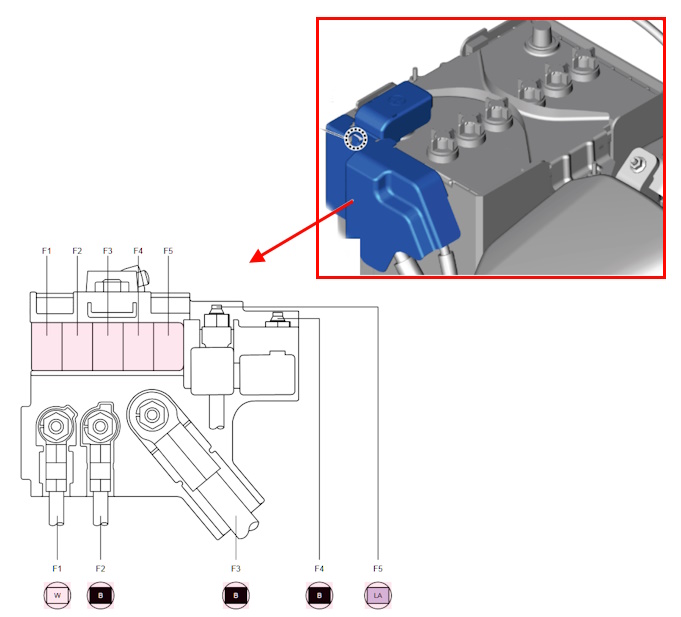
Assignment
| F1 | 80 A — DC-DC (SKYACTIV-G), GLOW/DC-DC (SKYACTIV-D) |
| F2 | 80 A — FAN (SKYACTIV-X, SKYACTIV-D) |
| F3 | 200 A — MAIN |
| F4 | 200 A — ALT/ST (SKYACTIV-G, SKYACTIV-X) 250 A — ALT/ST (SKYACTIV-D) |
| F5 | 200 A — DC-DC (SKYACTIV-X) 100 A — PTC (SKYACTIV-D) |
There is a video on this topic on our channel.