The 8th generation Hyundai Sonata was produced in 2019, 2020, 2021, 2022, 2023, 2024, 2025, 2026, 2027, 2028, 2029 with the DN8 index. During this time, the model has got facelift. In our article you can find a designation of the fuses and relays of the Hyundai Sonata 8G with fuse box diagrams, their locations and photo examples of execution. Let’s highlight the fuse responsible for the cigarette lighter.

The purpose of fuses and relays, as well as their number, may differ from those presented and depend on the year of manufacture and the level of electrical equipment of your car.
Passenger compartment
Inside the car, the fuse box is located in the lower left part of the instrument panel.

Type 1
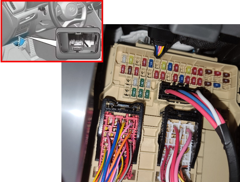
To gain access to the unit, you must remove the protective cover. On the reverse side of which is the current diagram.

Diagram

Assignment
| S/HEATER (FRT) | 25A Heated Front Seat Control Module, Front Ventilated Seat Control Module |
| TRUNK | 10A ICU Junction Block (Trunk Lid Relay) |
| DOOR LOCK | 20A ICU Connection Block (Door Lock Relay, Door Unlock Relay, Two Turn Unlock Relay) |
| MODULE1 | 7.5A Key Solenoid |
| MODULE3 | 10A Driver Door Module, Passenger Seat Relax Unit, Hazard Switch, Hazard Panel Switch (Up), Front Lamp Assembly, Start/Stop Button Switch, Driver/Passenger Smart Key External Handle |
| S/HEATER (RR) | 25A Rear seat heating control module |
| P/SEAT (PASS) | 30A Passenger Seat Manual Switch, Passenger Seat Relaxation Unit |
| MODULE6 | 10A Driver Door Module |
| SAFETY P/WINDOW (RH) | 30A Passenger Safety Power Window Module, Right Rear Power Window Switch |
| P/SEAT (DRV) | 30A Driver Seat Manual Switch, Driver IMS Module |
| IBU1 | 15A IBU, Driver/Passenger Door NFC Module, IAU, BLE Unit, Ignition Switch |
| AMP | 25A AMP DC/DC converter (AMP) |
| SAFETY P/WINDOW (LH) | 30A Driver Safety Power Window Module Rear Power Window Switch Left |
| BRAKE SWITCH | 10A IBU, brake light switch |
| SUNROOF2 | 20A Panoramic sunroof, data link connector |
| AIR BAG2 | 10A SRS control module |
| AIR BAG1 | 15A SRS control module, passenger detection sensor |
| E-SHIFTER1 | 10A SCU, electronic ATM shift lever |
| MEMORY | 10A Driver IMS Module, Security Indicator Light, A/C Switch, Driver/Passenger Power Outside Mirror, A/C Control Module, Instrument Cluster, Rain Sensor, Head-Up Display |
| MULTI MEDIA | 15A Audio, AV and Navigation Head Unit, DC/DC Converter (AMP/Audio) |
| SUNROOF1 | 20A Panoramic sunroof |
| MODULE7 | 10A Front Console Switch, Lane Keeping Assist Unit, IBU, Hazard Panel Switch (Up/Down), Avodance Parking Assist Unit, Intelligent Parking Assist Unit with Remote Control |
| MODULE5 | 10A Brake light switch |
| MODULE8 | 10A Front Heated Seat Control Module, Front Ventilated Seat Control Module, Passenger Seat Relaxation Module, Amplifier, Rear Seat Heat Control Module, Driver IMS Module, Audio, A/V and Navigation Head Unit |
| E-SHIFTER2 | 10A SCU, electronic ATM shift lever |
| MODULE2 | 10A IAU, Parking Anti-Collision Control Module, Cooling Fan Motor, Passenger Seat Relaxation Module, Rear Seat Heater Control Module |
| MDPS | 7.5A MDPS Department |
| A/C | 7.5A A/C Control Module, A/C Switch, E/R Junction Block (Fan Relay, PTC Heater Relay) |
| MODULE4 | 10A Front USB Charger, Rear USB Charger, AMP, IBU, IAU, Parking Collision Avoidance System, Audio System, DC/DC Converter (AMP/Audio), A/V & Navigation, Head Unit, Around View Monitor Unit |
| MODULE9 | 7.5A IBU |
| CLUSTER | 10A Instrument cluster, head-up display |
| WASHER | 15A Multifunction switch, Washer |
| START | 7.5A PCM/ECM, E/R Junction Block (Start Relay), ICU Junction Block (B/Alarm Relay) |
| POWER OUTLET | 20A Front socket, Cigarette lighter |
| IBU2 | 7.5A IBU |
| A/BAG IND | 7.5A Instrument cluster, overhead console lamp (lamp) |
The front cigarette lighter is controlled by a fuse marked POWER OUTLET.
Type 2
Photo – example

Diagram

Description
| SPARE | Spare fuse |
| MODULE | Electronic control module |
| MODULE 4 | ATM Shift Lever IND., AMP, Driver IMS Control Module, DC-DC Converter, CCNS Head Unit, Data Link Connector, Smart Phone Wireless Charger Unit, A/C Switch, A/C Control Module, Overhead Console, Electro Chromic Mirror |
| A/C | Air conditioning system |
| BRAKE SWITCH | Brake pedal switch |
| CCU | Central/Body Control Unit |
| TRUNK OPEN | Trunk lid opener circuit |
| WASHER | Windshield washer pump |
| P/SEAT (PASS) | Front passenger power seat |
| P/SEAT (DRIV) | Driver power seat |
| S/HEATER (FR) | Front seat heater |
| S/HEATER (RR) | Rear seat heater |
| P/WINDOW (LH) | Left power window |
| P/WINDOW (RH) | Right power window |
| DOOR LOCK | Central door locking system |
| POWER TRUNK | Power trunk actuator |
| BDC | Body Domain Controller |
| AMP | Audio system amplifier |
| START | Engine start circuit |
| MEMORY | Memory functions (seat/mirror settings) |
| Wireless DCU | Wireless communication control unit |
| BDC 2 | Secondary body control unit |
| MULTIMEDIA | Multimedia / infotainment system |
| SUNROOF | Power sunroof |
| AIR BAG | Airbag (SRS) system |
| USB CHARGER | USB charging ports |
| CLUSTER | Instrument cluster |
| MDPS | Motor Driven Power Steering (EPS) |
| LDC | Driver assistance / camera system |
| SHIFTER | Gear selector / shift control |
| DCU | Data / Drive Control Unit |
Engine compartment
Under the hood in the engine compartment on the left side there is a main block with fuses and relays.
Photo – example
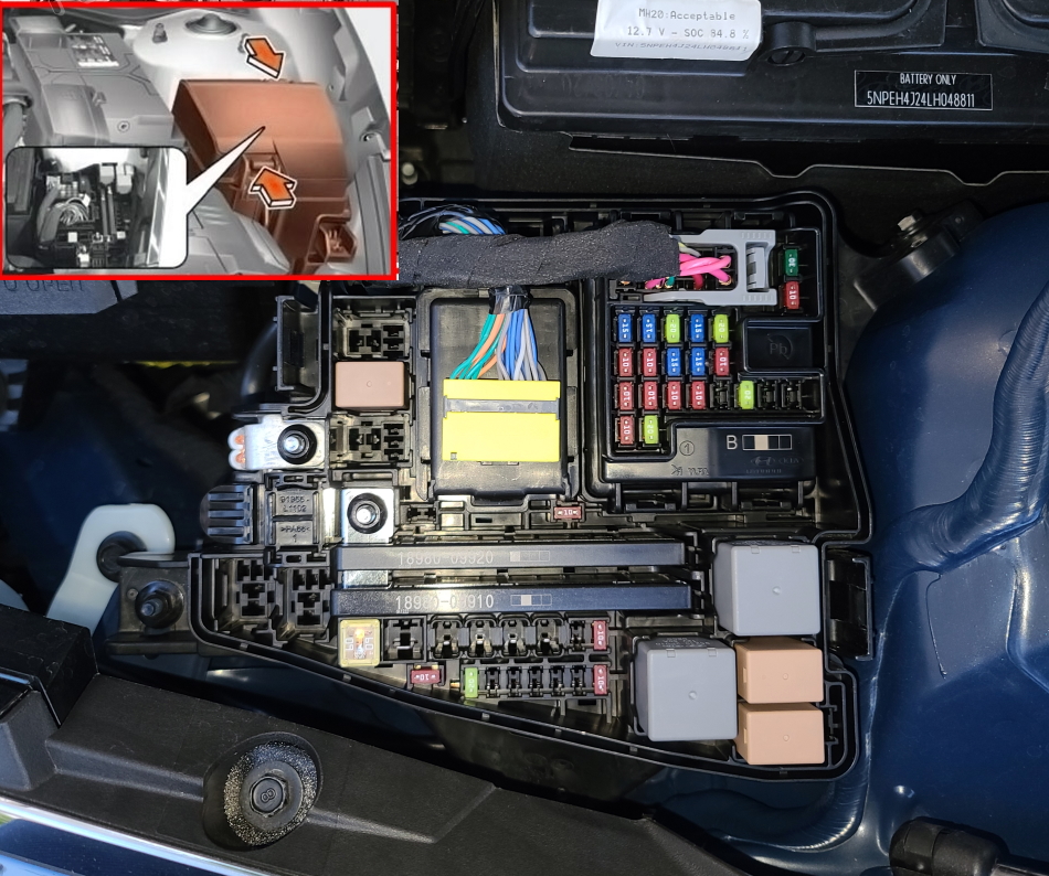
Check the information with your diagrams on the block cover.
Diagram

Designation
| IG2 | 30A E/R connection block (start relay), PCB block (IG2 relay) |
| BLOWER | 40A E/R Junction Block (Fan Relay) |
| ABS1 | 40A ABS module |
| B+2 | 50A ICU Distribution Block (IPS4, IPS3, IPS1, Fuse – AMP, IBU1) |
| PTC HEATER | 50A E/R Junction Block (PTC Heater Relay) |
| B+3 | 50A ICU Connection Block (IPS5, IPS7, IPS9, IPS10, IPS8, IPS6) |
| OIL PUMP1 | 50A Electronic Oil Pump |
| COOLING FAN | 80A Cooling Fan Motor |
| MDPS | 80A MDPS Department |
| E-SHIFTER | 30A SKU |
| E-CVVT1 | 40A G4FN: CVVD DRIVE; |
| E/R connection block (E-CVVT relay) | |
| IG1 | 40A PCB unit (IG1 relay, ACC relay) |
| REAR HEATED | 50A Connection block E/R (rear heating relay) |
| EPB | 60A ECU module |
| B+5 | 60A PCB Assembly (Engine Control Relay, Fuse – A/C1, WIPER1, TCU1, Horn, ECU2) |
| B+1 | 60A ICU Distribution Block (fuse – P/SEAT (DRV), P/SEAT (PASS), MODULE1, SAFETY P/WINDOW (LH), SAFETY P/WINDOW (RH), S/HEATER (RR)) |
| HEATED MIRROR | 10A Driver/Passenger Power Outside Mirror, A/C Switch, A/C Control Module, ECM |
| ECU5 | 10A G4FN: ECM |
| AMS | 10A Battery Sensor |
| FUEL PUMP 1 | 20A E/R Connection Block (Fuel Pump Relay) |
| A/C 2 | 10A Air Conditioning Control Module |
| B+4 | 60A ICU Junction Block (Ltd Load Latch Relay, Fuse – MODULE 3, AIR BAG 2, E-SHIFTER1, HUNCH 1, HOOK 2, S/HEATER (FRONT), TRUNK, BRAKE SWITCH, DOOR LOCK) |
If you have anything to add to this post, write in the comments.
This is not for a 2024 Sonata. The fuse box on a ’24 looks completely different.