The 9th generation Honda Civic was produced in 2012, 2013, 2014, and 2015 with various body styles: sedan, coupe, hatchback and station wagon. In this article you can find a description of the fuses and relays for the Honda Civic 9 with fuse box diagram, locations and photo examples. Select the cigarette lighter fuse.

The American sedan and coupe and the European hatchback and station wagon were very different from each other, both in terms of the general layout and technical content, so the purpose of the fuses and relays in the blocks may differ from those presented.
Passenger compartment
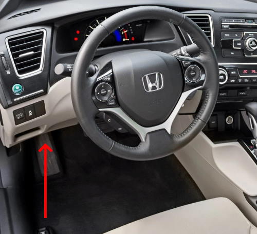
In the passenger compartment, the main fuse and relay box is located under the instrument panel on the driver’s side.

Photo example

Diagram

Assignment
| 1 | 20A HAC (hill assist system) |
| 2 | 10A ACG (ignition) |
| 3 | 10A SRS |
| 4 | 15A Fuel pump |
| 5 | 7.5A Instruments |
| 6 | 7.5A Power window |
| 7 | 15A VB SQL |
| 8 | 15A Door lock motor 2 (unlock) |
| 9 | 15A Door lock motor 1 (unlock) |
| 10 | 10A Daytime outdoor lighting |
| 11 | 20A Luke |
| 12 | 15/20A Accessory socket (center console) |
| 13 | 20A Power seats |
| 14 | 15A Seat heaters |
| 15 | 10A Driver’s door lock motor (unlock) |
| 16 | – |
| 17 | – |
| 18 | – |
| 19 | 7.5A AC |
| 20 | 7.5A ACC key lock |
| 21 | 7.5A Daytime running lights |
| 22 | 7.5A HAC |
| 23 | 7.5A HAC |
| 24 | 7.5A ABS/VSA |
| 25 | 7.5A AC |
| 26 | – |
| 27 | 15/20A Accessory power socket (front), cigarette lighter |
| 28 | 15A Washer |
| 29 | 7.5A ODS |
| 30 | 10A Driver’s door lock motor (lock) |
| 31 | 10A Smart |
| 32 | 15A Door lock motor 2 (lock) |
| 33 | 15A Door lock motor 1 (lock) |
| 34 | 7.5A Small lights (dimensions) |
| 35 | 7.5A Lighting |
| 36 | Reserve |
| 37 | 20A Power seats |
| 38 | 10A High beam left headlight |
| 39 | 10A High beam right headlight |
| 40 | 7.5A Rear fog light |
| 41 | 20A Lock |
| 42 | 20A Driver window regulator |
| 43 | 20A Power window, rear passenger side |
| 44 | 20A Power window, passenger side |
| 45 | 20A Rear power window, driver’s side |
| 46 | 30A Wiper |
| – | 7.5A STS |
| R1 | Power window relay |
| R2 | Fuel pump relay |
| R3 | Starter relay |
| R4 | |
| R5 | Fuel injection relay |
| R6 | Power window relay |
Check the designation of elements with your diagrams.
An example of a diagram with a designation

Engine compartment
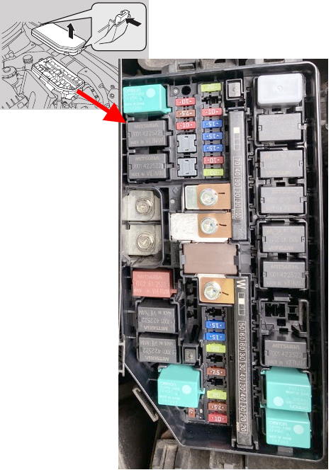
Under the hood, the main fuse and relay box is located on the left side and is covered with a protective cover.

An example of a circuit from the box cover

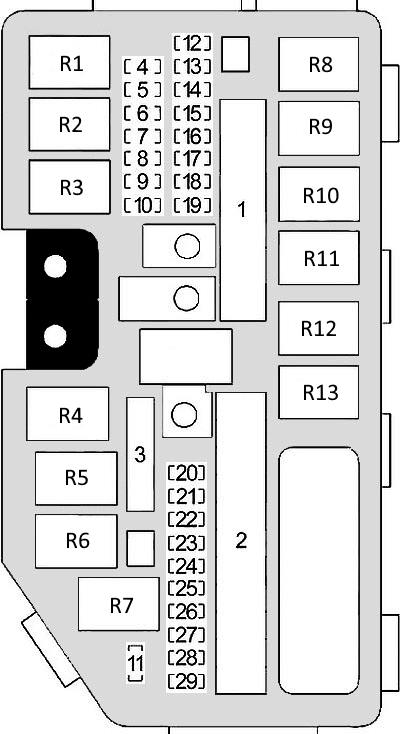
Diagram

Allocation
| 1 | 70A EPS (Power Steering) |
| 30A ABS/VSA Motor | |
| 30A ABS/VSA FSR | |
| 30A Cleaner motor | |
| 100A Main fuse | |
| 2 | 30/50A IG main |
| 60A Main fuse box | |
| 60A Main fuse box 2 | |
| 30A Headlight main fuse | |
| 30A ST/MG switch | |
| 30 Rear heater | |
| 30A IG Primary 2 | |
| 40A Fan | |
| 20F Auxiliary fan motor | |
| 20F Main fan motor | |
| 3 | – |
| 4 | 15A Dipped beam left headlight |
| 5 | 7.5A ST DIAG/ ST MG |
| 6 | 15A Dipped beam right headlight |
| 7 | – |
| 8 | – |
| 9 | – |
| 10 | – |
| 11 | 7.5A Oil level |
| 12 | 20A Fog lights |
| 13 | 20A Power sliding driver’s seat |
| 14 | 10A Alarm |
| 15 | 15A FI Sub |
| 16 | 15A IG ignition coil |
| 17 | 15A Stop lights |
| 18 | 10A Horn |
| 19 | 20A Trailer electrical equipment |
| 20 | 15A Low beam injector, right headlight |
| 21 | 15A IGP |
| 22 | 15A DBW |
| 23 | 15A Dipped beam left headlight |
| 24 | 20A Power driver seat |
| 25 | 7.5A Clutch |
| 26 | 15A Washer |
| 27 | 20A Marker lamps |
| 28 | 7.5A Interior lighting |
| 29 | 10A Reversing lamp |
| R1 | Heater Fan Relay |
| R2 | Starter relay 1 |
| R3 | Auxiliary Fan Relay |
| R4 | Ignition coil relay |
| R5 | Starter relay 2 |
| R6 | Injection relay |
| R7 | Rear heater relay |
| R8 | Fan speed relay (high / low) |
| R9 | Main fan relay |
| R10 | Wiper relay |
| R11 | Magnetic clutch relay |
| R12 | Front fog lamp relay |
| R13 | Horn relay |
We have also posted a video for this post on our YouTube channel. Watch and subscribe to the channel.
Is there anything to add material? Write in the comments.
 FuseAndRelay.com
Hola, quisiera saber cuál de los reley de la caja de fusible del motor es el reley de aceleración ?
I want to know where the starter relay is located in Honda civic 2012.